

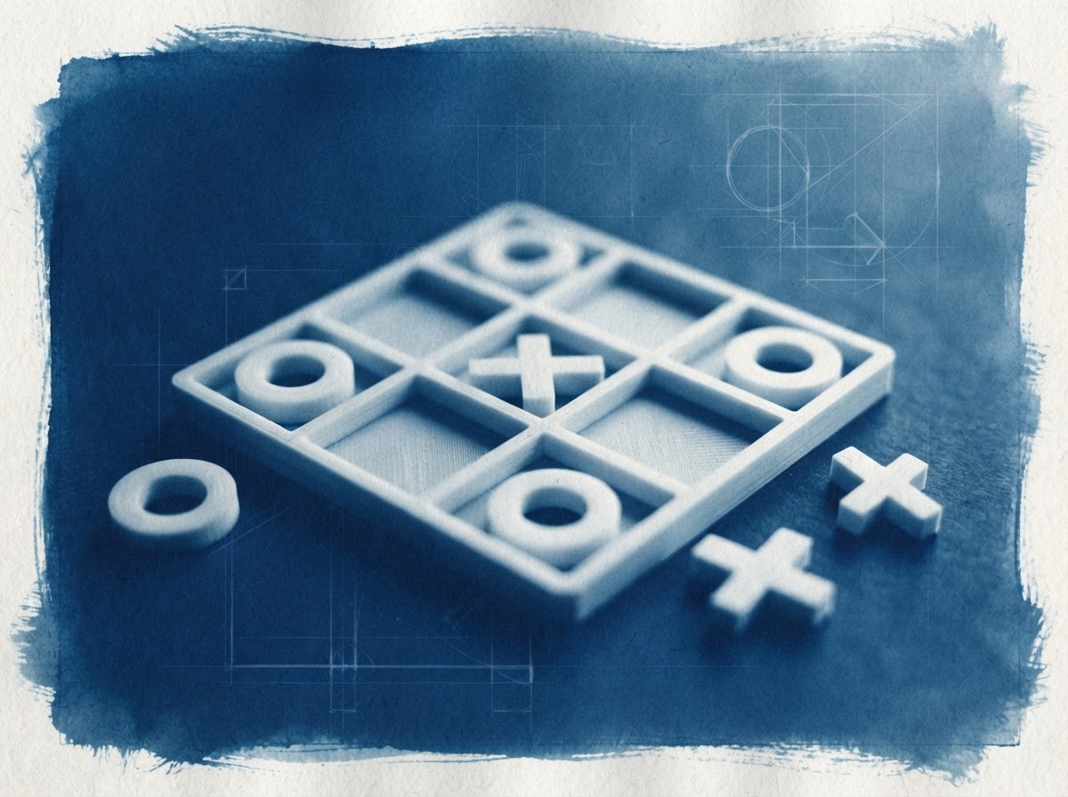
It’s time to put a full stop on my tic-tac-toe robot arm project, at least for now. Over the last few weeks it has grown from “can I get the arm to touch nine squares?” into a working game. An Arduino drives the arm, an AI picks the moves, a camera watches the board, and a set of 3D-printed pieces is designed to be gripped and recognised by colour. Everything now lives in two projects in my GitHub repo, 44-tic-tac-toe-arm and 45-board-camera, along with the board and piece models.
This post wraps the whole thing up in one place. I’ll cover what was built, how it fits together end to end, how it was wired, what I learned and what’s still unfinished. If you want to build your own, every file I mention links straight to the source.
Catching up on the series
If you’re new to the project, here’s the trail of earlier posts on CIAOPS Labs:
- Next Project: Teaching My Robot Arm to Play Tic-Tac-Toe: the idea and the plan.
- Step One: Teaching the Arm Where the Board Is: servo calibration, the first real build step.
- Playing a Full Game with Minimax and Gemini: the game logic.
- How Minimax Plays Perfect Tic-Tac-Toe: A Worked Guide: the algorithm explained.
- Board, Pieces and the Next Pickup Step: the printed board and counters.
- Now Picking Its Own Pieces: the video of the arm collecting its own pieces.
The arm itself goes back further. I covered building it in Building a 6DOF Programmable Robot Arm and Robot Arm with Multi Motor Movement.
What was built
At the highest level there are three pieces, and the top-level README lays them out the same way:
- The arm (project 44). An Arduino UNO R4 WiFi drives six servos directly. It runs the game, hosts its own web pages and talks to Gemini.
- The camera (project 45). An AI-Thinker ESP32-CAM looks down on the board, works out which cells hold a red X, a yellow O or nothing, and serves that as a nine-character string.
- The playing field (3d-models/tictactoe). A 180×180 mm printed board and weighted counters designed for the gripper and the camera.
The human always plays yellow O and the robot always plays red X. That isn’t just a style choice. The camera tells the pieces apart by colour, so it matters.
How it was assembled: the component layout
The diagram below is the full layout and connection map, drawn only from what the published firmware and READMEs actually state. Click it for the full-resolution version.
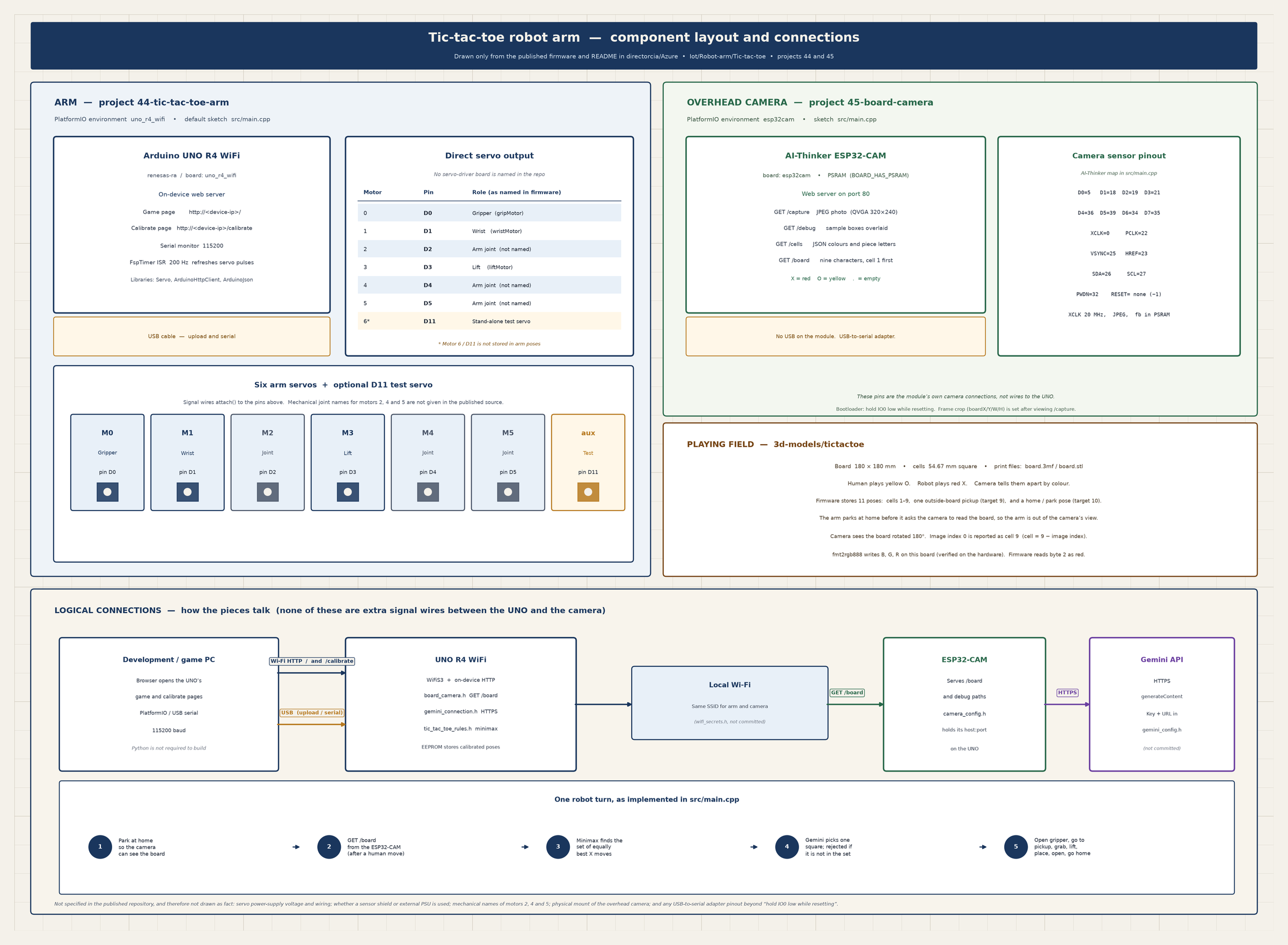
There are really two kinds of connection here. The first is physical. Six servo signal wires run from the UNO, plus an optional test servo. A USB cable connects the PC to the UNO, and a USB-to-serial adapter is used to program the ESP32-CAM. The second is over the network. The UNO and the camera join the same Wi-Fi, and the UNO asks the camera for the board with a plain HTTP request. There are no signal wires between the UNO and the camera at all.
Here is the servo wiring as it is defined in src/main.cpp (motorPins[] = {0, 1, 2, 3, 4, 5}, auxPin = 11):
| Motor | UNO R4 pin | Role in the firmware | Notes |
|---|---|---|---|
| M0 | D0 | Gripper (gripMotor) | Home pose = gripper open; closed = open − gripAmount (15°) |
| M1 | D1 | Wrist (wristMotor) | Per-square wrist compensation applied at clearance height |
| M2 | D2 | Arm joint | Name not given in the source |
| M3 | D3 | Lift (liftMotor) | Clearance angle 90°; lifts first, lowers last |
| M4 | D4 | Arm joint | Name not given in the source |
| M5 | D5 | Arm joint | Name not given in the source |
| Aux | D11 | Stand-alone test servo | Not part of the arm poses; jog it from /calibrate |
And the camera side. These are the AI-Thinker module’s own on-board camera connections, set in 45-board-camera/src/main.cpp. You don’t wire them yourself, but they’re worth knowing if you swap boards:
| Signal | GPIO | Signal | GPIO |
|---|---|---|---|
| D0 / D1 | 5 / 18 | XCLK (20 MHz) | 0 |
| D2 / D3 | 19 / 21 | PCLK | 22 |
| D4 / D5 | 36 / 39 | VSYNC / HREF | 25 / 23 |
| D6 / D7 | 34 / 35 | SCCB SDA / SCL | 26 / 27 |
| PWDN | 32 | RESET | not used (−1) |
One thing to be upfront about: the repo doesn’t document the servo power supply. It doesn’t say how the servos get their power, whether a shield or external supply sits between the UNO and the servos, or how the camera is mounted above the board. I’ve deliberately left those off the diagram rather than guess. My earlier arm builds used a Keyestudio sensor shield, but this project’s source doesn’t confirm that, so treat power as something you’ll need to size for your own servos.
How it works end to end
A robot turn runs through a fixed sequence, and each step lives in a specific file:
- Park and look. After the human places a yellow O, the arm moves to its home pose so it’s out of the camera’s view. It waits about 500 ms to settle, then calls
GET /boardon the ESP32-CAM usingboard_camera.h. It tries up to three times and needs two identical readings in a row before it trusts the result. - Check what changed.
camera_board_diff.hcompares the camera’s view with the board the arm already knows about. Exactly one new O is accepted as the human’s move. A missing X, no change, or several changes are rejected with a message rather than guessed at. - Minimax finds the best moves.
tic_tac_toe_rules.hruns a full minimax search and returns every square that is equally best for X, not just one. - Gemini picks one.
gemini_connection.hsends the board and that list of equal-best squares to Gemini over HTTPS and asks for JSON back, in the form{"square":N}. If Gemini returns a square that isn’t in the minimax set, the firmware rejects it and the arm doesn’t move. The AI adds variety, but it can never make a bad move. - The arm moves. It opens the gripper at home, goes to the off-board pickup point and grabs the piece. Then it lifts to clearance, travels, sets the wrist angle for that square, lowers straight down, releases and goes home. If it wins, there’s a victory jig.
The bit I’m happiest with is how the motion is timed. Servo positions are recalculated in a 200 Hz FspTimer interrupt, so a slow Wi-Fi call to Gemini or the camera never freezes the arm halfway through a move. Calibrated poses are stored in EEPROM, so the arm remembers them through a power cycle.
The UNO also serves two web pages. The game page at / is where you play and watch the live output. At /calibrate you can jog each servo, test poses and store the 11 targets: cells 1 to 9, the pickup point and home. The serial commands from the earlier tic_tac_toe.cpp still work too.
The camera
The camera firmware is compact, and you can read the whole thing in one sitting. It captures a 320×240 JPEG, decodes it and averages the colour over the middle half of each of the nine cells, which keeps the grid lines out of the sample. It then sorts each cell into one of three groups:
- Empty when red minus blue is under 30.
- Yellow O when green is more than 0.8 times red.
- Red X otherwise.
It exposes /capture (the photo), /debug (the photo with sample boxes drawn on), /cells (JSON with the colour values) and /board (the nine characters the arm reads, for example X...O....).
Two hardware quirks cost me time and are now written into the code. First, fmt2rgb888 on this board writes bytes in blue-green-red order, not red-green-blue, so byte 2 is red. That was checked on the actual hardware. Second, the camera sees the board rotated 180 degrees, so image index 0 is reported as cell 9. Get either one wrong and the arm will confidently respond to a game nobody is playing.
The printed board and pieces
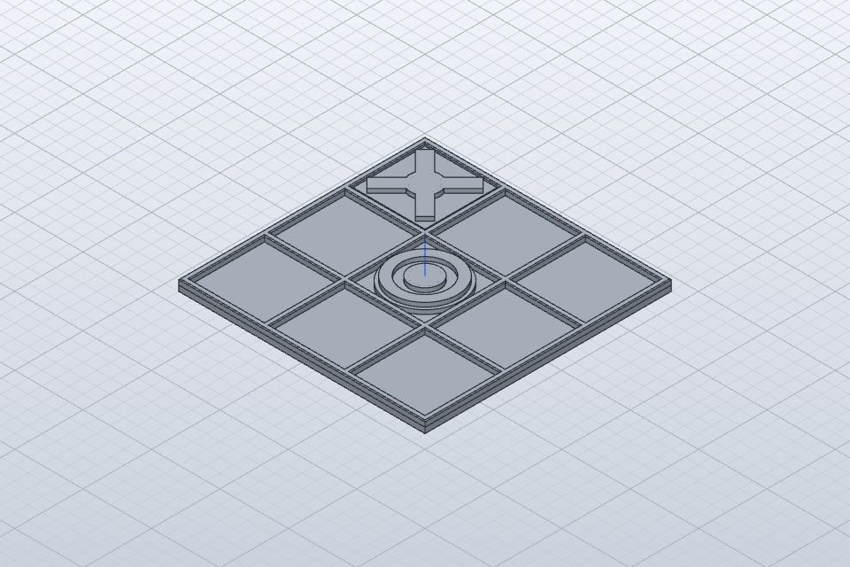
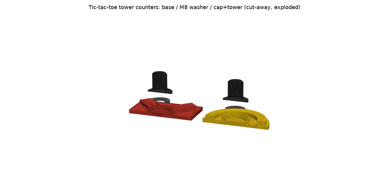
The models README has the details. The board is board.stl / board.3mf at 180×180 mm with 54.67 mm cells. tictactoe_all.3mf packs the board with one X and one O. The one-piece counters (counter_X.stl, counter_O.stl) have a sealed pocket for an M8 washer. You pause the print at Z 5.4 mm, drop the washer in and resume. The extra weight helps the pieces sit flat and release cleanly from the gripper.
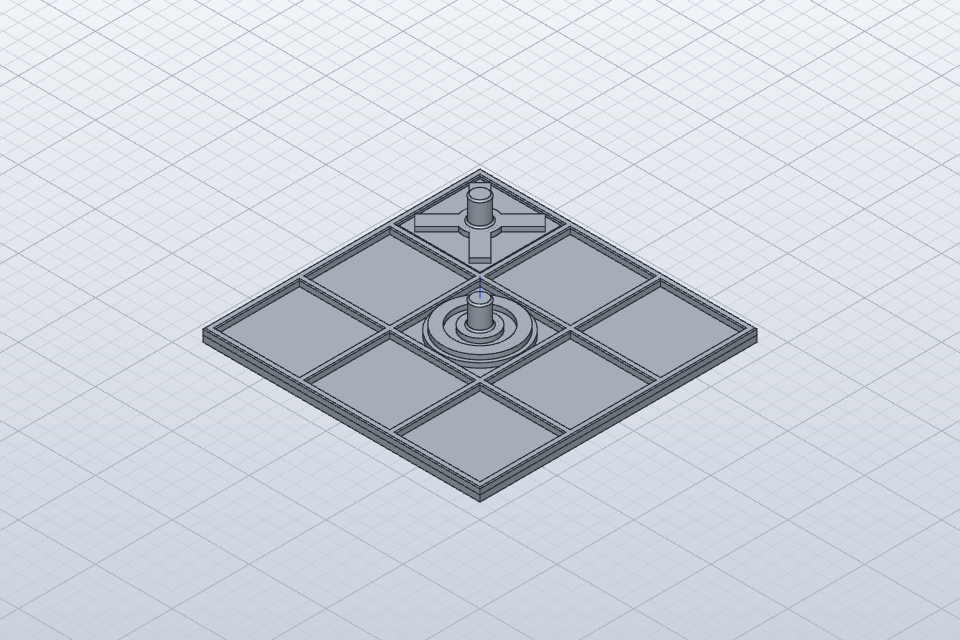
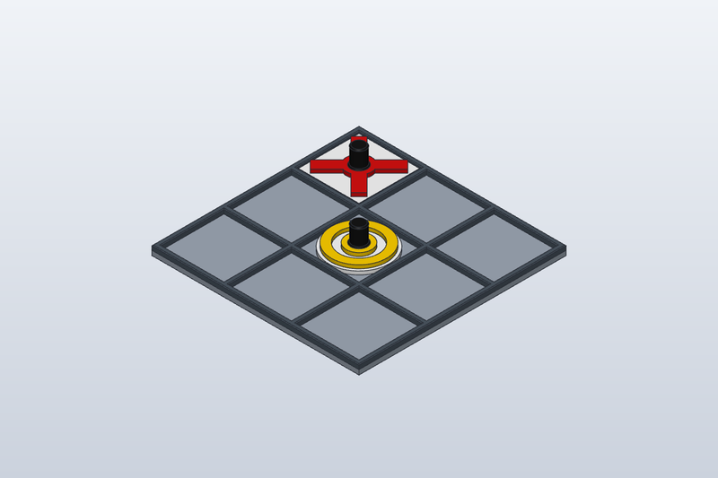
If you’d rather not pause mid-print, the two_part folder has glue-together base and cap versions, including ones sized for a 10 mm washer. The editable source is tictactoe.solidcraft.
Building it yourself
Both projects are PlatformIO projects with their own platformio.ini (arm, camera). The short version:
- Copy the templates in
44-tic-tac-toe-arm/include:wifi_secrets_example.h,gemini_config_example.handcamera_config_example.h. Fill in your own Wi-Fi details, Gemini key and URL, and the camera’s address. None of these are committed to the repo. - Build and upload the arm with
pio run -e uno_r4_wifi -t upload. - Copy
wifi_secrets_example.hin45-board-camera/include, then build and upload the camera withpio run -e esp32cam -t upload. The module has no USB port, so use a USB-to-serial adapter and hold IO0 low while resetting. - Open
/captureand adjust the crop valuesboardX,boardY,boardWandboardHuntil the board fills the frame. Then put the camera’s IP address intocamera_config.h. - Calibrate the 11 poses on
/calibrate. This is the step that takes the most patience.
The arm project also has smaller test environments: cell_sequence for a motion-only demo, plus mapping, gemini and tictactoe. They’re handy for testing one layer at a time (cell_sequence.cpp, mapping.cpp, gemini_test.cpp).
What got finished in projects 44 and 45
- A camera-integrated game firmware, built from
main.cppby default, with a web game page and a calibration page. - Motion driven by a timer interrupt, so network calls don’t stall the servos.
- Minimax as a guard on Gemini’s choices, with a built-in self-test covering wins, draws, invalid moves, openings, forced wins and blocks, and fork defence.
- Wrist compensation for each square, so pieces arrive straight instead of rotated. README_WRIST_COMPENSATION.md and CALIBRATION_GUIDE.md explain it.
- Perpendicular descent, so the arm lowers straight down onto a square instead of swinging in at an angle (PERPENDICULAR_DESCENT_FIXED.md).
- A camera that reads the board, debounced readings and a strict rule for accepting a move.
- Print-ready board and counters, plus the editable SolidCraft source.
- A clean public release, with secrets moved into gitignored local headers.
Lessons learned
- The logic is the easy part. Minimax for tic-tac-toe is a few dozen lines. Getting a hobby servo arm to grab a small piece the same way every time is where most of the hours went.
- Let the AI choose, but check its answer. Giving Gemini a list of moves minimax has already approved, and rejecting anything outside it, keeps the game interesting without trusting a language model to play perfectly.
- Keep timing-critical work away from the network. Moving servo updates into a timer interrupt was what made Wi-Fi and the arm work together.
- Write down your hardware quirks. The BGR byte order and the 180-degree rotation are each one line in the code, and each one would have broken the game without anyone noticing.
- Small bugs hide in plain sight. For a while the wrist compensation never ran, because the code reset a variable to zero before checking it (CRITICAL_BUG_FOUND_AND_FIXED.md).
- Never assume the camera is right. Requiring two identical readings and exactly one new piece stops a shadow or a bumped piece from being taken as a move.
What’s left
I said this wraps the project up “for now”, and I meant it. A few things are still open:
- The camera is still a work in progress. The firmware reads the board, but the colour thresholds and crop are tuned for my lighting and my mount. It needs more testing before I’d call it reliable.
- Piece holders. The arm currently picks every X from a single pickup point outside the board. The next step is a set of fixed holders off the board, so the arm can collect from several slots in turn without me reloading it.
- Calibration polish. The wrist compensation values in the code are a calibrated estimate. Each square could be fine-tuned further, and gripper settings are still the main cause of the occasional missed pickup.
- Power and mounting notes. The repo should eventually document the servo supply and the camera mount, so someone else can reproduce the build without guessing.
What could come next
A few ideas I’d like to try when I come back to it. One is letting the arm clear the board itself at the end of a game. Another is moving from fixed colour thresholds to something that adapts to the lighting. I’d also like to use the camera to check that the arm actually dropped its piece in the right square. And I want to try the same arm, camera and game-logic pattern on a different game. The structure is general: a camera that turns the physical board into a string, a rules engine that defines what’s legal, an AI that chooses within those rules, and an arm that makes it happen.
That’s the real takeaway for me. Each layer is simple on its own. The value comes from joining them up carefully, with checks between each step. If you build your own version, I’d love to see it. Grab the code from my tic-tac-toe folder on GitHub and let me know how you go.


