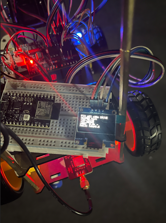
Acebott robot car with GPS driving
I’ve been busy on another robot car project. This time I wanted to take the Acebott standard QD001 project and combine it with the QD009 GPS add on and have it navigate using GPS. This turned out to be harder than expected.
The main learning was that GPS isn’t really accurate enough to assist with robot car movement, due to the extremely small distances that the car travels. However, what I wanted to achieve was to have the robot car at least head north as a test.
The first big change from previous robot car projects was to change the wheels from mecanum to normal wheels. This is because the car would now be outside on much rougher terrain and didn’t need the ability to move sideways. Basically it just needed to drive around, so normal wheels it was.
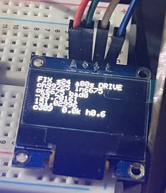
During the initial debug process I added an OLED screen, which I kept, so I could try and see what was going on with the car during movement. In the end that didn’t work to well, especially given how small the OLED screen was. For much better debugging I logged movement data to an adafruit.io data feed. That meant that the car needed Internet access, which I provided by hot spotting my phone.
It took much back and forth with AI to eventually end up with code that did what I wanted. You’ll find the code here:
https://github.com/directorcia/Azure/blob/master/Iot/Acebott/Smartcar/QD009/gps.ino
What gps.ino does
This is an Arduino/ESP32 sketch for an ACEBOTT QD009 four-wheel smart car (an ESP32 board with a 74HC595 motor shield). It fits a GPS module, an OLED display and WiFi telemetry. Its main job is a “drive north” test. The car has no compass, so it uses only GPS to work out which way it’s heading, then steers itself until it’s travelling north.
Hardware and libraries
- TinyGPS++ parses the NMEA sentences from the GPS module, which is wired to GPIO 27 (RX only, since the TX pin is
-1) at 9600 baud.
- Adafruit SSD1306/GFX drives a 128×64 OLED over I2C (SDA 21, SCL 22).
- WiFi and Adafruit MQTT publish a log line to an Adafruit IO feed called
car-log.
telemetry_secrets.hholds the WiFi and Adafruit IO credentials. It’s gitignored, so it isn’t in the repo.
esp_system.hand thesoc/rtc_cntl_regheaders are used for reset-reason diagnostics and for disabling the brownout detector.
Motor control
The motors aren’t driven directly. Two PWM pins set speed (GPIO 19 for the right side, GPIO 23 for the left), and a 74HC595 shift register sets direction. The code shifts out one byte whose bits select forward or reverse for each of the four motors. For example, DIR_FORWARD = 163 (0xA3) and DIR_SPIN_LEFT = 83 (0x53).
setMotors() is the core function. It records the last command, applies the motor trim, sets the PWM, and latches the direction byte into the shift register.
Trim: the left and right motors don’t produce equal thrust, so the car drifts. motorTrim (default 85) boosts the left PWM and reduces the right PWM, scaled by speed relative to the speed it was calibrated at (200). Trim is deliberately not applied during in-place spins. Unequal sides would make the car arc instead of rotate, so turn angles would differ by direction.
turnPwm() forces spins up to at least 240 PWM, because a 4WD skid-steer car stalls on low-power spins.
The GPS “drive north” state machine
handleGpsNorthTest() is a non-blocking state machine that runs from loop(). It starts automatically at boot (AUTO_GPS_NORTH_ON_BOOT) or when you press n.
-
WAIT_FOR_FIX: The car stays stopped until it has a valid GPS location newer than 5 seconds. It then requires the fix to be held continuously for 2.5 s. It records that position as the baseline, then starts driving forward at PWM 155.
-
DRIVE_FORWARD: It drives for 5.5 s. While moving, it samples the receiver’s own course-over-ground, but only if speed is at least 1.5 km/h. Below that, the receiver’s course is noise. After 5.5 s it stops.
-
COMPARE: After a 2.8 s settle to let GPS update, it works out which way the car actually went:
- It computes the distance and bearing from the baseline to the new position.
- If the car moved at least 3 m, it trusts the displacement bearing, because GPS position noise is about 2-3 m and a bearing from a shorter move is essentially random.
- Otherwise it falls back to the receiver’s Doppler-derived course sampled while driving, if there is one.
- If it has neither, it doesn’t guess. It drives forward again to build a longer baseline.
- The heading error is that heading wrapped to ±180°, since north is 0°. If the error is within ±28° (
GPS_COURSE_TOLERANCE_DEG), the car is going north, so it resets the baseline and drives on. Otherwise it turns.
- It computes the distance and bearing from the baseline to the new position.
-
TURN: This is an open-loop turn with no feedback during the turn itself. Duration is
error ÷ 90°/s, clamped between 180 ms and 1400 ms. If the error is positive (east of north) it spins left, and if negative it spins right. A code comment says this was previously inverted, which made the car spiral away from north. After the turn it goes back to WAIT_FOR_FIX to take a fresh baseline, because the old one is stale.
Safety: after 8 consecutive turns without success, it stops (GPS_MAX_CONSECUTIVE_TURNS). Any manual drive command also cancels the test.
In short, the car drives a bit, measures how it moved, corrects by a calculated turn, and repeats.
OLED display
handleLcd() refreshes every 400 ms and shows:
- WiFi status.
- GPS lock state (
FIX,NMEAif data is arriving but there’s no fix, orNO), satellite count, fix age and current mode.
- Checksum pass and fail counts.
- Latitude and longitude.
- Current course, speed, last turn direction (L/R), last travel heading and HDOP.
It’s also fault-tolerant:
recoverI2CBus()bit-bangs up to 9 clock pulses to free a stuck SDA line, which happens if the OLED powers up more slowly than the ESP32.
- Every 2 s it checks that the display still acknowledges on the bus. If it doesn’t, it re-initializes without needing a power cycle.
- If init fails, it retries every second indefinitely.
Telemetry
handleWifi() reconnects in the background without ever blocking. handleTelemetry() runs every 10 s (to stay under Adafruit IO’s free-tier rate limit) and publishes a single log string to the car-log feed. It contains uptime, mode, state, lat/lng, heading, satellites, NMEA counts, checksum stats, turn count and turn direction. The same line goes to the serial monitor.
Diagnostics and robustness
- Brownout detector disabled (
WRITE_PERI_REG(RTC_CNTL_BROWN_OUT_REG, 0)): a weak battery could otherwise cause a silent reset loop during boot.
- Boot counter in RTC memory (
RTC_DATA_ATTR bootCount) survives software and brownout resets. A rising count without a physical power cycle means the board is reset-looping.
- LED blink codes (
blinkDiagnostic) flash the reset-reason code, then the boot count, so you can diagnose problems even if the OLED stays blank.
- External LEDs show status: slow alternating means no GPS data, fast alternating means NMEA bytes are arriving, and both solid means the motors are driving in the north test.
Serial commands
Key
Action
w s a d
Forward, backward, spin left, spin right
space / x
Stop everything
t
Wheel diagnostic: runs six tests (forward, back, spins, left-only, right-only)
b
Timed 4 s straight run to measure drift for trim calibration
[ ]
Adjust trim by -1 / +1
p
Print trim
c
Toggle continuous loop test (forward, back, spin left, spin right, with pauses)
g
Toggle raw NMEA output
n
Start or stop the GPS north test
+ -, 1–5
Change speed (presets 160, 185, 210, 235, 255)
h / ?
Help
Setup and loop
setup() runs in this order: disable brownout, increment the boot count, start serial, blink diagnostics, init motors, OLED, GPS and WiFi, then a 3-second countdown. If auto-start is enabled, it then arms the north test.
loop() calls each handler in turn (serial commands, continuous test, LEDs, GPS parsing, OLED, north state machine, WiFi, telemetry), toggles the heartbeat LED each second, and sleeps 8 ms. Nothing blocks, so GPS parsing, the display and WiFi all keep running while the car drives. The exception is the blocking delayWithExternalLedFlash() used in the diagnostic routines, which at least keeps parsing GPS and updating the display while it waits.
Limitations
- GPS course only works while moving, and accuracy is about 3 m, so this suits open outdoor areas and not indoors.
- The turns are open-loop and rely on a measured 90°/s yaw rate, so surface and battery level will affect accuracy. The state machine corrects for that by re-measuring after each turn.
- The car starts moving on its own about 3 s after boot once it has a fix, so keep it clear of obstacles.
Nanoblock Shuri Castle
ESP-Now Beacon fail
I have been trying to build something that will allow my robot car to navigate autonomously to a beacon indoors.
The first attempt at this using Bluetooth didn’t work:
https://blog.ciaopslabs.com/2026/08/02/bluetooth-beacon-fail/
mainly because Bluetooth doesn’t have enough range.
The second attempt using ESP-Now (radio) has also not really worked, this time mainly due to the signal reflections indoors.
Initially, I started off by just swapping out the Bluetooth beacon code for the ESP-Now code but that didn’t seem to actually work. I then simplified it down to just a beacon and a responder. In effect, I replicated a sonar system where the responder would beep faster the closer it got to the beacon.
After plenty of testing I discovered that the reflections due to the indoors environment made it next to impossible to get reliable directions using this process. I have however uploaded the bacon code here:
https://github.com/directorcia/Azure/blob/master/Iot/LLM/beacon.ino
and the responder code here:
https://github.com/directorcia/Azure/blob/master/Iot/LLM/llm-sonar.ino
the recommended solution is to use UWB, which would mean at least 2 senors like this:
https://core-electronics.com.au/challenger-rp2040-uwb-dwm3000.html
which aren’t cheap if I am just testing.
Another option is to move the project to using robot vision, which I was going to get to and have done before. However, I’m going to have a think about whether this is the direction I want to go or perhaps it is time to try something new?
LEGO Technic Ducati Panigale V4 S Motorcycle
Bluetooth Beacon fail
After getting my robot car to navigate autonomously around the next challenge was to have it hone in on a beacon. The initial suggestion was to use another Acebott ESP32 broadcasting a repeated Bluetooth signal.
In short, this ended up failing simply because the Bluetooth signal was simply not strong enough across any meaningful distance (that is, greater than 2 metres).
It want to make this project work and the suggested next options is to use something called ESP-NOW.
ESP-NOW: Direct Device-to-Device Communication for ESP32 Projects
What is ESP-NOW?
ESP-NOW is a proprietary wireless communication protocol developed by Espressif that allows ESP32 and ESP8266 devices to communicate directly with each other without requiring a Wi-Fi router, access point, or internet connection.
Think of it as a lightweight, low-latency messaging system that uses the ESP32’s Wi-Fi radio to exchange data directly between devices.
Key Benefits
- No Wi-Fi network required
- Low latency communication
- Low power consumption
- Simple device-to-device messaging
- Works alongside Wi-Fi in many scenarios
- Native support on ESP32 hardware
- Typical range often exceeds BLE
How It Works
Rather than sending data through a router:
ESP32 —> Router —> ESP32
ESP-NOW allows direct communication:
ESP32 <—–> ESP32
Each device is identified by its MAC address, allowing messages to be exchanged directly.
Typical Uses
ESP-NOW is popular for:
- Robot-to-robot communication
- Sensor networks
- Remote controls
- Home automation
- Wireless telemetry
- Drone communications
- IoT projects requiring low latency
For ESP32-to-ESP32 projects, ESP-NOW is often preferred over BLE when communication range and update frequency are important.
Using ESP-NOW for Robot Navigation
A robot can receive regular beacon packets from a stationary ESP32 and use that information to estimate whether it is moving closer to or further away from the destination.
Example:
-85 dBm = Far
-70 dBm = Closer
-55 dBm = Very Close
Limitations
ESP-NOW provides:
✅ Fast communication
✅ Good range
✅ Direct device-to-device connectivity
ESP-NOW does not provide:
❌ Precise distance measurements
❌ Direction information
❌ Indoor positioning
For navigation applications, RSSI values can be affected by:
- Walls
- Furniture
- Metal objects
- Reflections
- People moving through the environment
Why ESP-NOW Matters
For ESP32-based projects, ESP-NOW offers a simple and effective way to exchange data between devices without the complexity of Wi-Fi networking. It is particularly useful when low latency, low power consumption, and direct communication are more important than internet connectivity.
For robotics, ESP-NOW can provide a low-cost method for building wireless beacons, sharing telemetry, and coordinating multiple robots using hardware many makers already have available.
Apparently, I can use ESP-NOW and still have the Robot car connected to the Internet via Wifi. Given that it won;t cost me anything except some time to code, let’s see how we go.
Simulation for improvement
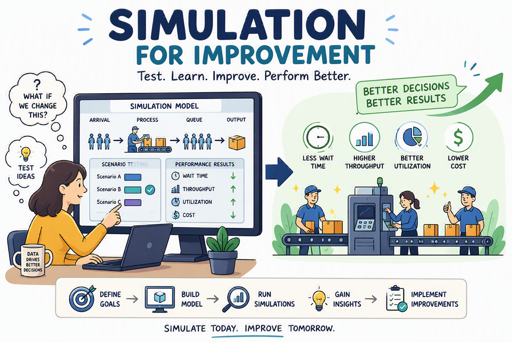
If you have been following along with my robot car guided by AI project you’ll know that I got it working with Gemini. I then switched to using Azure AI Foundry. Finally, I changed the code so that car ran most of the local decisions while the AI just made the major navigation decisions.
Each time navigation did improve, but I would have to observe the movements and tell the AI what issues I’d seen and then the Ai would go off and improve the code. I’d then test and update again, round and round in a loop. Each time there was a small incremental change in navigation ability but I still faced edge cases the existing algorithm struggled with.
I could have continued this update, observe, update loop infinitum, making constant incremental improvements. However, when I stepped back and though about how AI systems improve I realised that it was via repetitive learning in a simulated, rather than real environment.
I therefore asked Github Copilot to simulate the algorithm of the robot cars navigation and then test that via simulation. Any improvements learned via the simulation should then be applied back to the robot cars code. I then unleashed Github Copilot to complete this task, without asking for input, until it reached a near prefect navigation result in the simulator.
The result is this code:
https://github.com/directorcia/Azure/blob/master/Iot/LLM/llm-nav-max.ino
which I will say, although far from ‘perfect’ achieved much better results than the incremental ones I was obtaining simply by observational feedback.
The success I’ve had here using the concept of a simulation to test the algorithm and then continue to iterate to improve the code has made me think about what else I could apply this ‘simulation’ process to when other AI work I am performing.
Interesting.
Having the AI make make better decisions
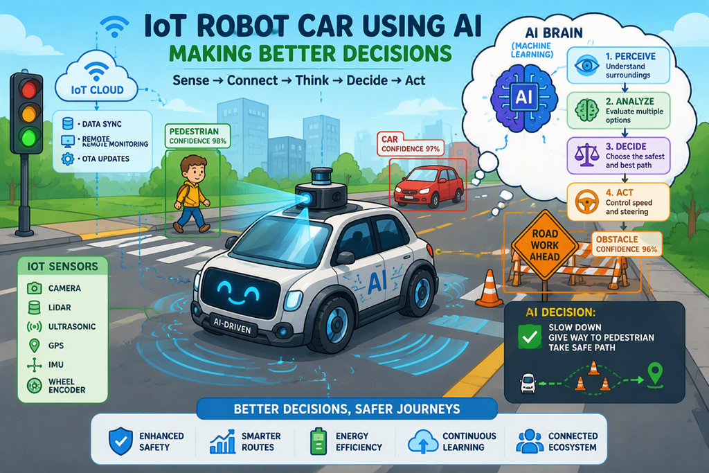
After some Ai prompting it was suggested that my robot car navigation would improve if the car did more itself with local routines and only used the AI when it could not decide so I plugged away and ended up with this code:
https://github.com/directorcia/Azure/blob/master/Iot/LLM/llm-nav-max.ino
you will see:
An ESP32 robot car drives forward until its ultrasonic sensor (mounted on a pan servo) detects an obstacle. On each hazard event a two-tier decision pipeline fires:
1. LOCAL PLANNER – scores three candidate maneuvers (strafe, 90° turn, and backup+turn) using live L/F/R distance readings, front-clearance trend, and oscillation history. If the result is “obvious” (high confidence, low risk, no repeated-trap condition) it is executed immediately without any network round-trip.
2. FOUNDRY ARBITER – when the local answer is ambiguous, or a repeated-trap is detected, a structured prompt is posted to an Azure AI Foundry Responses API endpoint. The LLM names one candidate plan and returns a confidence score. The response is validated and sanitized; any failure falls back to the local plan.
After every maneuver the robot re-scans, records the front-clearance delta, and feeds plan quality (improved / worsened) back into the next decision cycle.
After a quick test, navigation does seem more intelligent, although it seems to make decisions a long way away and tends to get lost in wide open spaces with object far away. However, I think that if I nvested more time I could improve all that.
I have an additional idea on how I might improve the navigation in an upcoming article, but for now I think I’m pretty much done with the concept of navigation.
Connecting the robot car to Azure AI Foundry
If you have been following along you will know that I’ve connected a robot car to both a local LLM and cloud based Gemini. The last iteration is here:
https://blog.ciaopslabs.com/2026/07/18/controlling-a-robot-car-with-ai/
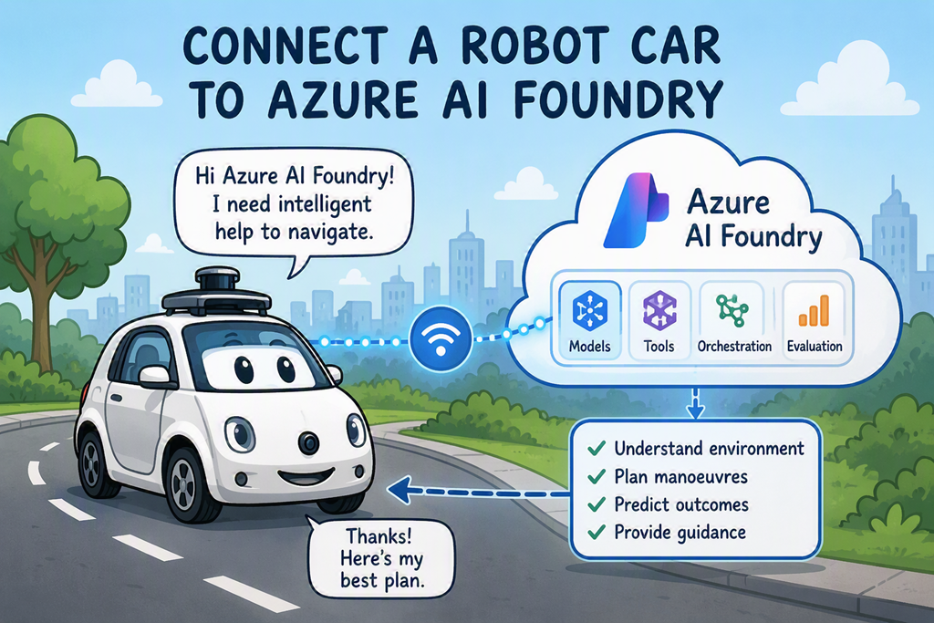
I decided that I should connect the car to Azure AI Foundry because there are so many more models available as well as everything else that comes with Azure.
So I set up a simple Foundry project
Step 1: Create an Azure AI Foundry Project
- Browse to Azure AI Foundry:
- Sign in with your Azure account.
- Select:
- Create Project
- Project Name:
RobotNavigation
- Create or select:
- Azure Subscription
- Resource Group
- Azure AI Services Resource
- Azure Subscription
- Wait for deployment to complete.
Step 2: Deploy a Model
Within your Foundry project:
- Open:
Model Catalog - Deploy:
- GPT-5-mini
- GPT-5.1-mini
- GPT-4.1-mini
- GPT-5-mini
For a robot car:
GPT-5-mini
is usually sufficient and inexpensive.
Step 3: Obtain Connection Details
From Foundry copy:
Endpoint URL
API Key
Model Name
C++
#define FOUNDRY_RESPONSES_URL \
“https://robot-navigation-resource.services.ai.azure.com/openai/v1/responses”
#define FOUNDRY_MODEL “gpt-5-mini”
The recommendation was the use the gpt-5-mini model, so I plugged it into the existing code, made a few improvements and ended up with this:
https://github.com/directorcia/Azure/blob/master/Iot/LLM/llm-foundry.ino
My observation is that the navigate is generally better but the delays are longer when it has to ‘thinlk’ (aka go to the LLM). This has to do with the size of model, basically gpt-5-mini vs gemini3-flash.
So, the lesson here is I need the smallest possible model for the job. For now I’ll stick with gpt-5-mini.
So more research indicates that I shoudl probably offload more processes to the local device and only the LLM at a much higher level. A better plan seems to bei instead of asking the LLM to invent a manoeuvre plan, ask it to choose from local candidate plans you already created.
So let me go and try that now.
Controlling a robot car with AI
After having AI show my fortune, the next project was having AI navigate my robot car.
To keep things simple I constrained movement to a 5 x 5 grid ( X = 0 – 4 and Y = 0 – 4) and the car could only move N, S, E or W one cell at a time. To get the algorithm right and test this with Ai before actually applying it to the car I simulated the result on the OLED screen I had previously configured.
With that all working I upgraded the code to run with the robot car and you’ll find it here:
https://github.com/directorcia/Azure/blob/master/Iot/LLM/llm-cellmove.ino
The main issue I found was more mechanical with the robot car wheels dragging and not being very precise, so the car woudl easily wander off in different directions. This has more to do with teh quality of the motors and wheels as well as the friction encountered when the wheels start moving. However, aside from that the test worked successfully and the car cycled up the grid and then back down.
Next, I wanted the AI to actually assist with the navigation of the car. I went through plenty of iterations with this. The most important change is that I moved from using a local AI to using Gemini via API calls. The main reason for this was simply speed. As the prompts became larger the local AI model struggled to return the results to the car in enough time to implement effective navigation. I had also wanted to integrate large cloud based LLM so here was the opportunity, so I hooked up Gemini.
The robot car also has an ultrasonic senor connected to a motor at the front so I could sweep it left and right as well for better object detection. However, initially I kept it simple and all on teh car by just using the ultrasonic sensor to detect hazards and try to makeover around them. The code for that is here:
https://github.com/directorcia/Azure/blob/master/Iot/LLM/llm-sweep.ino
I then upgraded the code to integrate the LLM into the navigation process by making decisions on which direction to turn. That code is here:
https://github.com/directorcia/Azure/blob/master/Iot/LLM/llm-sweep.ino
One issues I ran into, that wasted a lot of my time and was totally my own fault, was when I started having issues with the wheel moving the car forward. I blamed the code but in fact, again it was a hardware issue, being the battery charge had become too low to actually drive the wheels acceptably. It is interesting at how quickly that car now actually drains power when fully running.
With the power issues resolved I upgraded the code a number of times to allow the LLM a much higher level of navigation control. You’ll find the final result here:
https://github.com/directorcia/Azure/blob/master/Iot/LLM/llm-assist-nav.ino
The end result of all these experiments is that I have learned that in the full configuration the car now burns a lot of power as it moves, turns the sensor, communicates over wifi and more. all the changes I made to the code would make the car slightly less likely to crash into objects on the floor but a lot more though needs to go into ‘crash free’ navigation. The obvious improvement is to add more sensors to provide the LLM with more information to make better decisions. I also found that the wheel on the car are not precise enough and don’t really provide the best grip. This means they tend to be slow to engage and lag cause the car to veer.
I think all of these can be solved iteratively over time and I am confident that I can get to a situation that allows the robot car to move pretty much crash free around the floor just like a robot vacuum can already. However, the time required is probably not something that I’m willing to invest in just now to get a little incrementally better. I’m happy that my ‘proof of concept’ when it comes to navigation with LLMs works. I think it is time to move onto the next project.