Tic-Tac-Toe Robot Arm Update: Board, Pieces and the Next Pickup Step

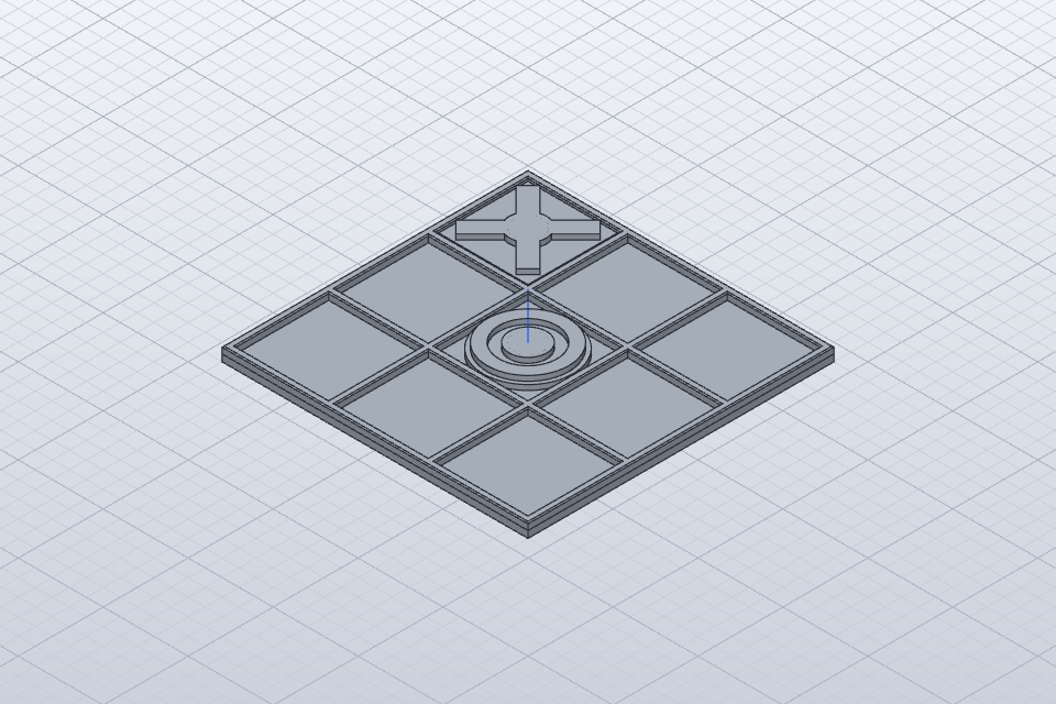
Repository render of the board and X/O pieces
Repository render of the board and X/O pieces. This is a model preview, not a photograph of the printed build. Full-resolution image.

The board and playing-piece models are now included in my tic-tac-toe robot arm project on GitHub. The project brings together the arm firmware, the ESP32-CAM companion and the printable game components. The camera is still a work in progress. My next step is to give the arm a set of fixed off-board positions from which it can collect its pieces and place them on the board.

What is in the project

The top-level README groups the work into three folders:

  • 44-tic-tac-toe-arm/ — PlatformIO project for an Arduino UNO R4 WiFi. Six arm servos, with motor 0 as the gripper, drive the poses. Motion is updated on a timer so Wi-Fi and camera HTTP calls do not freeze the servo plan mid-move. The sketch serves game and calibrate pages on the board, and it can ask the camera for a board reading.
  • 45-board-camera/ — Separate PlatformIO project for an AI-Thinker ESP32-CAM with PSRAM. It is meant to serve the board state the arm consumes, including GET /board and related paths such as /capture, /debug and /cells.
  • 3d-models/tictactoe/ — Board and piece meshes, preview images and the SolidCraft source. The print files live here rather than inside the arm firmware folder.

Open the arm and camera folders as separate PlatformIO projects — each has its own platformio.ini. Wi-Fi details, API keys and the camera address stay on the machine as local copies of the *_example.h templates. Those filled-in headers are gitignored.

Board and piece models

The models folder README names the print files and how they fit together:

  • Board: board.3mf and board.stl — 180×180 mm. The 3MF has Board_Base and Board_Grid. Each cell is 54.67 mm square. tictactoe_all.3mf packs the board with one flat X and one flat O.
  • One-piece counters: counter_X.stl and counter_O.stl for the flat pieces, plus tower variants counter_X_tower.stl and counter_O_tower.stl, and matching *_tower_parts.3mf files. The one-piece counters include a sealed pocket for an M8 washer; the README says to pause at Z 5.4 mm, drop the washer, then resume so the top layers close the pocket.
  • Two-part counters: under two_part/, glue-together base and cap STLs and 3MFs, including versions sized for a 10 mm washer.
  • Editable source and previews: tictactoe.solidcraft, plus preview.png (board with flat counters — the image above), preview_tower.png, counters.png, counters_parts.png and the exploded two-part previews.

Print colour matches the game roles in the firmware: the human plays yellow O, the robot plays red X. The camera sketch is written to tell those colours apart, so printing in the right colours matters even while vision is unfinished.

How the current software plays a move

The default arm environment builds src/main.cpp, the camera-integrated game. Other environments in the same project cover a cell-sequence motion demo, board mapping, a Gemini connectivity test and a serial-only tic-tac-toe sketch without the camera client.

For each robot X, the documented sequence is: open the gripper at home, move to the pickup pose, close on the piece, lift clear, travel above the chosen square, orient the wrist while raised, lower, open to drop, lift clear and return home.

Move choice works in two stages. On-device minimax evaluates every legal X move and lists the equally best squares. Gemini then chooses among that list. If the returned square is not in the optimal set, or is occupied or invalid, the firmware rejects it and no motion runs. That check is about which square the robot is allowed to play. It does not, on its own, guarantee gripper grip, wrist calibration or a clean physical place.

Supply is still simple. Alongside the nine cell poses and the home/rest pose, the firmware keeps a single outside-board pickup pose. Before each robot move you need to have an X piece ready at that spot by hand. That is enough to exercise pick-and-place onto the board. It is not yet a set of fixed holders the arm can work through on its own.

Camera: still unfinished

The ESP32-CAM companion is in the tree with an AI-Thinker pinout, documented BGR colour handling, a 180-degree cell remap so image index 0 reports as cell 9, and the endpoints above. When the arm reads the board it parks first, waits briefly, then calls GET /board.

That path is still unfinished. Crop values (boardX, boardY, boardW, boardH) need adjusting after looking at /capture, and the game UI still lets you tap a square yourself if the camera reading is unsure. Treat vision as a work in progress, not a finished autonomous board reader.

Next: fixed off-board piece holders

The next mechanical step is to create designated piece holders at fixed positions off the board. Those holders are not in the models folder yet. The idea is that during play the arm collects each red X from one of those known off-board locations and places it on the relevant board square.

The nine board poses stay for dropping pieces into cells. The new holder poses are separate supply locations. With fixed holders, each robot move can come from a repeatable place: hover above a stocked holder, descend, close the gripper, lift with clearance, travel to the target cell hover pose, descend, open and retreat. Stock is no longer a single manually replenished spot.

When I build that stage I will need to work through the practical details:

  • Keep the board and holders physically fixed relative to the arm base so calibrated poses stay meaningful.
  • Define repeatable poses for each holder and each cell — approach and hover, grasp or drop height, and a lift height that clears the grid walls and other pieces.
  • Calibrate gripper open and close for the printed counters (flat or tower) so the jaws clear both the holder and the board grid.
  • Check reach and collision paths from each holder to each cell, not only the easy square in front of the arm.
  • Track which holders still contain pieces so the next robot move uses a stocked slot.
  • Keep the human’s yellow O pieces out of the robot’s red X supply.

I have not settled holder count or exact geometry yet. A sensible build-and-test order, once the holders exist on the bench, would be: mount the board and holders, extend the calibrate path so each holder pose can be configured, dry-run open and close at each holder without a piece, run real pick-and-place into empty cells from each holder, and only then fold multi-holder supply into a full game. Until that work lands, the single outside-board pickup remains the supply model in firmware, and the camera remains unfinished.

Earlier Labs posts

This sits on top of the earlier series: announcing the tic-tac-toe project, teaching the arm where the board is, playing with minimax and Gemini, and a worked minimax guide.

Links

With the board and piece models in the repo, the next bench job is those fixed holders — so the arm can collect its red Xs from known off-board positions and place them on the board while it plays.
Clearing a Blocked Snapmaker Artisan Nozzle: When You Have to Take the Hot End Apart

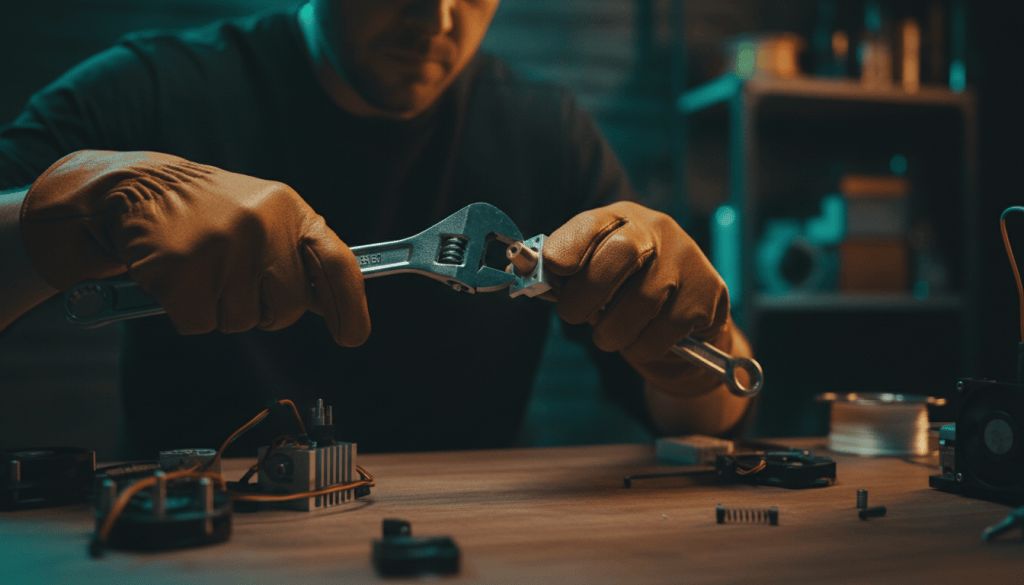
A maker carefully disassembling a 3D printer hot end on a workbench

There’s a particular sinking feeling when the Snapmaker Artisan starts a print, the nozzle moves happily across the bed, and nothing comes out. I’ve had it happen, and the temptation is to grab tools and start pulling things apart straight away. Don’t. Disassembly is the last resort, and Snapmaker says so itself. But when you genuinely need to go inside the hot end, you want the official steps, in the right order, without improvising. That’s what this post covers.

As I wrote in Why Everyone Needs Basic Technology Troubleshooting Skills, the simple checks come first. That applies to a 3D printer just as much as a laptop.

Symptoms of a blocked nozzle

Snapmaker’s How to replace the nozzle page lists the situations where the nozzle needs attention:

  • The nozzle is clogged and filament can’t be extruded.
  • Filament has leaked and filled the space between the nozzle and the heating block.
  • The nozzle is wrapped in a blob of filament that can’t be cleaned off.

Try the simple fixes first

Before reaching for a screwdriver, try unloading and reloading the filament. The official Dual Extrusion Module quick start guide describes the process: tap Control > Nozzle, select the nozzle, set the temperature and tap Heat. When it’s heated, tap Unload and pull the filament out, then insert the filament again and tap Load until it extrudes.

If filament has wrapped the heating block, Snapmaker’s Remove extruder blob guide says to heat the hot end, remove the blob with tweezers, wipe the block with a clean cloth and replace the silicone sleeve. A note of honesty: I couldn’t find an official Snapmaker cold pull procedure for the Artisan, so I won’t give you one here.

When disassembly is needed

Snapmaker’s How to disassemble the hot end of Dual Extrusion Module guide is for when filament is stuck in the nozzle, heat break or heat sink of the Artisan standard hot end and normal methods won’t clear it. Snapmaker rates it Difficult and warns that delicate parts can be damaged if you get the procedure wrong. Take your time.

Tools you’ll need

  • H1.5 screwdriver (the gray handled wrench provided by Artisan worked well for me) handled
  • 4″ adjustable wrench
  • 8″ adjustable wrench
  • A lighter (used in step 6 of the official guide)
  • High-temperature protective gloves, which the extruder blob guide recommends

Before you start

  1. Power off the machine before removing or refitting anything on the Dual Extruder. The official top cover kit guide says not to plug or unplug anything while the machine is on.
  2. Unload and pull the filament out of the module.
  3. Detach the hot end from the module. According to the extruder blob guide, you remove the print head bottom cover and front door panel, then loosen the bolts securing the lower hot end throat.

Disassembly: the hot side (heat break, heat block and nozzle)

  1. Remove the thermal insulating casing.
  2. Unplug the wires.
  3. Use the H1.5 screwdriver to loosen the two set screws on the heat block.
  4. Pull the heating rod and the thermistor sensor out of the heat block.
  5. Use the H1.5 screwdriver to loosen the set screw on the heat sink, then pull out the heat break.
  6. Clamp the heat block with the 8″ wrench and heat the nozzle with a lighter to melt any filament inside. If you skip this, Snapmaker warns the nozzle may be damaged when you unscrew it.
  7. Keep the heat block clamped with the 8″ wrench and use the 4″ wrench to unscrew the nozzle counterclockwise.
  8. Keep the heat block clamped with the 8″ wrench and use the 4″ wrench to unscrew the heat break counterclockwise.

Disassembly: the cold side (heat sink)

Only go this far if the blockage is higher up.

  1. Use the H1.5 screwdriver to loosen the set screw shown in the official guide.
  2. Clamp with the 8″ wrench and use the 4″ wrench to unscrew the upper throat tube counterclockwise.

The official page has photos for every step, and it’s worth keeping it open on a tablet beside you as you work.

Clearing the blockage

Snapmaker’s guide just says to carefully clean away the blockage once the parts are apart. It doesn’t specify any cleaning tools or methods, so I’d be careful and avoid forcing anything through the delicate parts. If a part is worn or damaged, the blob guide says to contact Snapmaker Support for a replacement rather than refitting it.

Reassembly

Snapmaker doesn’t publish separate reassembly steps for this guide. Its other module guides simply say to reinstall each part following the disassembly steps, so work backwards. For the nozzle itself, the nozzle replacement page (dual extruder method) does give specifics:

  1. Refit the upper throat tube and tighten its set screw, if you removed it.
  2. Screw the heat break back into the heat block.
  3. Point the heat block upwards. Align the nozzle with the hole in the heating block and tighten it clockwise.
  4. Clamp the heat block with one adjustable wrench and the nozzle with the other, then tighten the nozzle again.
  5. Slide the heat break back into the heat sink and tighten its set screw with the H1.5 screwdriver.
  6. Insert the heating rod and thermistor into the heat block and tighten the two set screws.
  7. Plug the wires back in, refit the thermal insulating casing, and refit the silicone cover.
  8. Refit the hot end in the module, tighten the lower throat bolts, and replace the bottom cover and front door panel. Then power on.

Snapmaker doesn’t publish torque values. Its official nozzle replacement video is a useful visual reference.

Testing and calibration afterwards

Don’t skip this step. The quick start guide says that every time you replace the hot end, you should redo the XY Offset Calibration and Z Offset Calibration. After reassembling the module, you should also redo Leveling. Swipe left on the Home Screen and tap Calibration. If the calibration model won’t print, Snapmaker’s Calibration Model printing failed page walks you through what to check. Load filament and confirm it extrudes cleanly before you trust it with a real job.

Prevention tips

  • Snapmaker’s replacement kit includes an upgraded front cover with ventilation holes. Snapmaker says it improves cooling around the hot end and reduces clogs.
  • Make sure the first layer sticks. Snapmaker lists poor first-layer adhesion as a cause of filament build-up around the nozzle.
  • Check that the nozzle and heat break are snug, because Snapmaker notes that a loose fit causes leaks.
  • Keep the Artisan troubleshooting hub bookmarked.

The lesson is the same one I keep coming back to in troubleshooting in general. Follow the documented process, change one thing at a time and verify the result. A little patience with the hot end saves a lot of grief, and a lot of spare parts.

References (official Snapmaker sources)

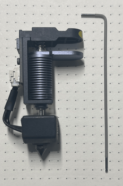
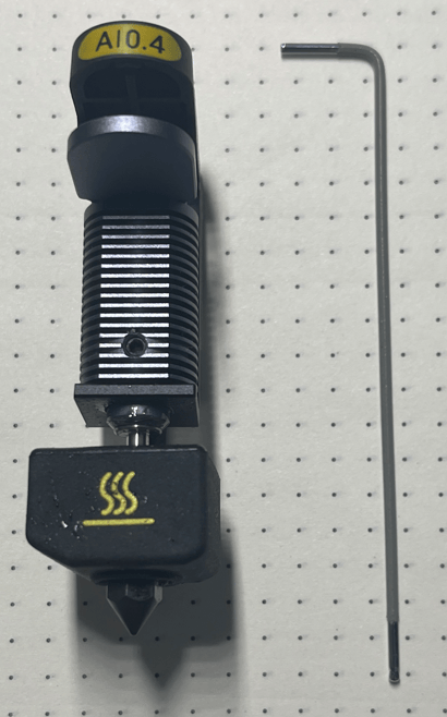
Print head and included tool used to allow disassembly