Acebott robot car with GPS driving

Screenshot 2026-10-03 214213

I’ve been busy on another robot car project. This time I wanted to take the Acebott standard QD001 project and combine it with the QD009 GPS add on and have it navigate using GPS. This turned out to be harder than expected.

The main learning was that GPS isn’t really accurate enough to assist with robot car movement, due to the extremely small distances that the car travels. However, what I wanted to achieve was to have the robot car at least head north as a test.

The first big change from previous robot car projects was to change the wheels from mecanum to normal wheels. This is because the car would now be outside on much rougher terrain and didn’t need the ability to move sideways. Basically it just needed to drive around, so normal wheels it was.
Screenshot 2026-10-03 213833

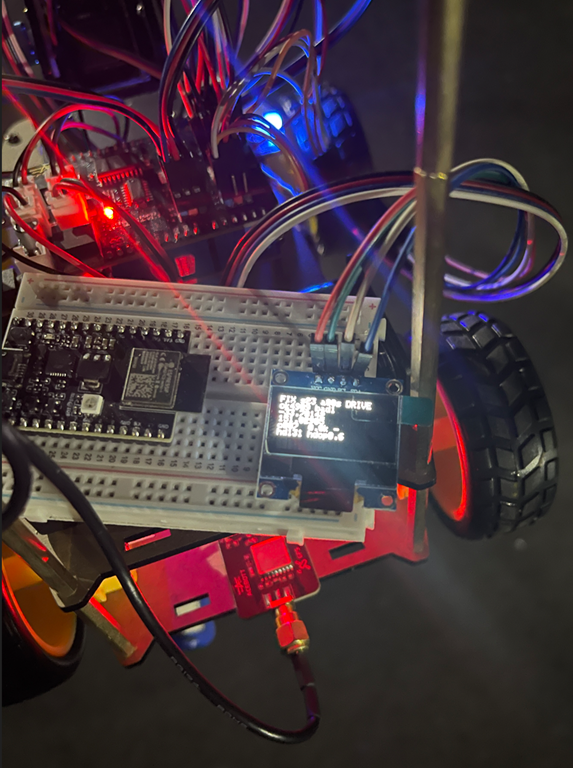
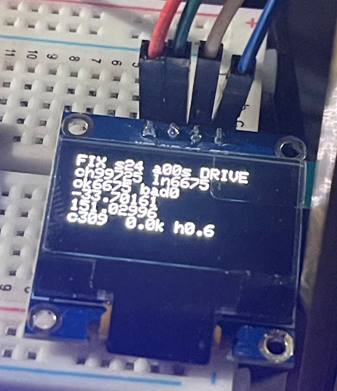
During the initial debug process I added an OLED screen, which I kept, so I could try and see what was going on with the car during movement. In the end that didn’t work to well, especially given how small the OLED screen was. For much better debugging I logged movement data to an adafruit.io data feed. That meant that the car needed Internet access, which I provided by hot spotting my phone.

It took much back and forth with AI to eventually end up with code that did what I wanted. You’ll find the code here:

https://github.com/directorcia/Azure/blob/master/Iot/Acebott/Smartcar/QD009/gps.ino

What gps.ino does

This is an Arduino/ESP32 sketch for an ACEBOTT QD009 four-wheel smart car (an ESP32 board with a 74HC595 motor shield). It fits a GPS module, an OLED display and WiFi telemetry. Its main job is a “drive north” test. The car has no compass, so it uses only GPS to work out which way it’s heading, then steers itself until it’s travelling north.

Hardware and libraries

  • TinyGPS++ parses the NMEA sentences from the GPS module, which is wired to GPIO 27 (RX only, since the TX pin is -1) at 9600 baud.

  • Adafruit SSD1306/GFX drives a 128×64 OLED over I2C (SDA 21, SCL 22).

  • WiFi and Adafruit MQTT publish a log line to an Adafruit IO feed called car-log.

  • telemetry_secrets.h holds the WiFi and Adafruit IO credentials. It’s gitignored, so it isn’t in the repo.

  • esp_system.h and the soc/rtc_cntl_reg headers are used for reset-reason diagnostics and for disabling the brownout detector.

Motor control

The motors aren’t driven directly. Two PWM pins set speed (GPIO 19 for the right side, GPIO 23 for the left), and a 74HC595 shift register sets direction. The code shifts out one byte whose bits select forward or reverse for each of the four motors. For example, DIR_FORWARD = 163 (0xA3) and DIR_SPIN_LEFT = 83 (0x53).

setMotors() is the core function. It records the last command, applies the motor trim, sets the PWM, and latches the direction byte into the shift register.

Trim: the left and right motors don’t produce equal thrust, so the car drifts. motorTrim (default 85) boosts the left PWM and reduces the right PWM, scaled by speed relative to the speed it was calibrated at (200). Trim is deliberately not applied during in-place spins. Unequal sides would make the car arc instead of rotate, so turn angles would differ by direction.

turnPwm() forces spins up to at least 240 PWM, because a 4WD skid-steer car stalls on low-power spins.

The GPS “drive north” state machine

handleGpsNorthTest() is a non-blocking state machine that runs from loop(). It starts automatically at boot (AUTO_GPS_NORTH_ON_BOOT) or when you press n.

  1. WAIT_FOR_FIX: The car stays stopped until it has a valid GPS location newer than 5 seconds. It then requires the fix to be held continuously for 2.5 s. It records that position as the baseline, then starts driving forward at PWM 155.

  2. DRIVE_FORWARD: It drives for 5.5 s. While moving, it samples the receiver’s own course-over-ground, but only if speed is at least 1.5 km/h. Below that, the receiver’s course is noise. After 5.5 s it stops.

  3. COMPARE: After a 2.8 s settle to let GPS update, it works out which way the car actually went:

    • It computes the distance and bearing from the baseline to the new position.

    • If the car moved at least 3 m, it trusts the displacement bearing, because GPS position noise is about 2-3 m and a bearing from a shorter move is essentially random.

    • Otherwise it falls back to the receiver’s Doppler-derived course sampled while driving, if there is one.

    • If it has neither, it doesn’t guess. It drives forward again to build a longer baseline.

    • The heading error is that heading wrapped to ±180°, since north is 0°. If the error is within ±28° (GPS_COURSE_TOLERANCE_DEG), the car is going north, so it resets the baseline and drives on. Otherwise it turns.
  4. TURN: This is an open-loop turn with no feedback during the turn itself. Duration is error ÷ 90°/s, clamped between 180 ms and 1400 ms. If the error is positive (east of north) it spins left, and if negative it spins right. A code comment says this was previously inverted, which made the car spiral away from north. After the turn it goes back to WAIT_FOR_FIX to take a fresh baseline, because the old one is stale.

Safety: after 8 consecutive turns without success, it stops (GPS_MAX_CONSECUTIVE_TURNS). Any manual drive command also cancels the test.

In short, the car drives a bit, measures how it moved, corrects by a calculated turn, and repeats.

OLED display

handleLcd() refreshes every 400 ms and shows:

  • WiFi status.

  • GPS lock state (FIX, NMEA if data is arriving but there’s no fix, or NO), satellite count, fix age and current mode.

  • Checksum pass and fail counts.

  • Latitude and longitude.

  • Current course, speed, last turn direction (L/R), last travel heading and HDOP.

It’s also fault-tolerant:

  • recoverI2CBus() bit-bangs up to 9 clock pulses to free a stuck SDA line, which happens if the OLED powers up more slowly than the ESP32.

  • Every 2 s it checks that the display still acknowledges on the bus. If it doesn’t, it re-initializes without needing a power cycle.

  • If init fails, it retries every second indefinitely.

Telemetry

handleWifi() reconnects in the background without ever blocking. handleTelemetry() runs every 10 s (to stay under Adafruit IO’s free-tier rate limit) and publishes a single log string to the car-log feed. It contains uptime, mode, state, lat/lng, heading, satellites, NMEA counts, checksum stats, turn count and turn direction. The same line goes to the serial monitor.

Diagnostics and robustness

  • Brownout detector disabled (WRITE_PERI_REG(RTC_CNTL_BROWN_OUT_REG, 0)): a weak battery could otherwise cause a silent reset loop during boot.

  • Boot counter in RTC memory (RTC_DATA_ATTR bootCount) survives software and brownout resets. A rising count without a physical power cycle means the board is reset-looping.

  • LED blink codes (blinkDiagnostic) flash the reset-reason code, then the boot count, so you can diagnose problems even if the OLED stays blank.

  • External LEDs show status: slow alternating means no GPS data, fast alternating means NMEA bytes are arriving, and both solid means the motors are driving in the north test.

Serial commands

Key
Action

w s a d
Forward, backward, spin left, spin right

space / x
Stop everything

t
Wheel diagnostic: runs six tests (forward, back, spins, left-only, right-only)

b
Timed 4 s straight run to measure drift for trim calibration

[ ]
Adjust trim by -1 / +1

p
Print trim

c
Toggle continuous loop test (forward, back, spin left, spin right, with pauses)

g
Toggle raw NMEA output

n
Start or stop the GPS north test

+ -, 1–5
Change speed (presets 160, 185, 210, 235, 255)

h / ?
Help

Setup and loop

setup() runs in this order: disable brownout, increment the boot count, start serial, blink diagnostics, init motors, OLED, GPS and WiFi, then a 3-second countdown. If auto-start is enabled, it then arms the north test.

loop() calls each handler in turn (serial commands, continuous test, LEDs, GPS parsing, OLED, north state machine, WiFi, telemetry), toggles the heartbeat LED each second, and sleeps 8 ms. Nothing blocks, so GPS parsing, the display and WiFi all keep running while the car drives. The exception is the blocking delayWithExternalLedFlash() used in the diagnostic routines, which at least keeps parsing GPS and updating the display while it waits.

Limitations

  • GPS course only works while moving, and accuracy is about 3 m, so this suits open outdoor areas and not indoors.

  • The turns are open-loop and rely on a measured 90°/s yaw rate, so surface and battery level will affect accuracy. The state machine corrects for that by re-measuring after each turn.

  • The car starts moving on its own about 3 s after boot once it has a fix, so keep it clear of obstacles.

ACEBOTT Smart car – Bringing it all together

blog

It is now time to bring all the pieces together on the Acebott Smart Car and make it a movable platform that can stream live video.

Screenshot 2026-01-04 101028

Screenshot 2026-01-04 101245

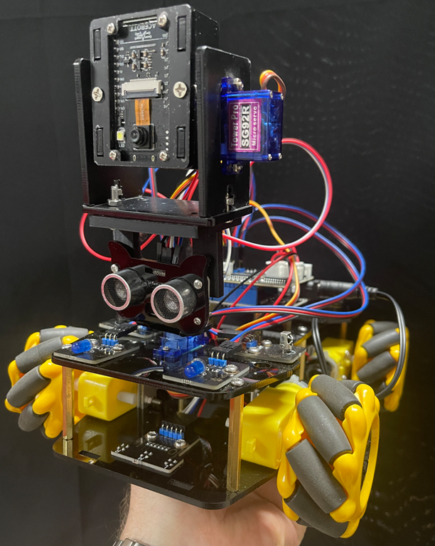
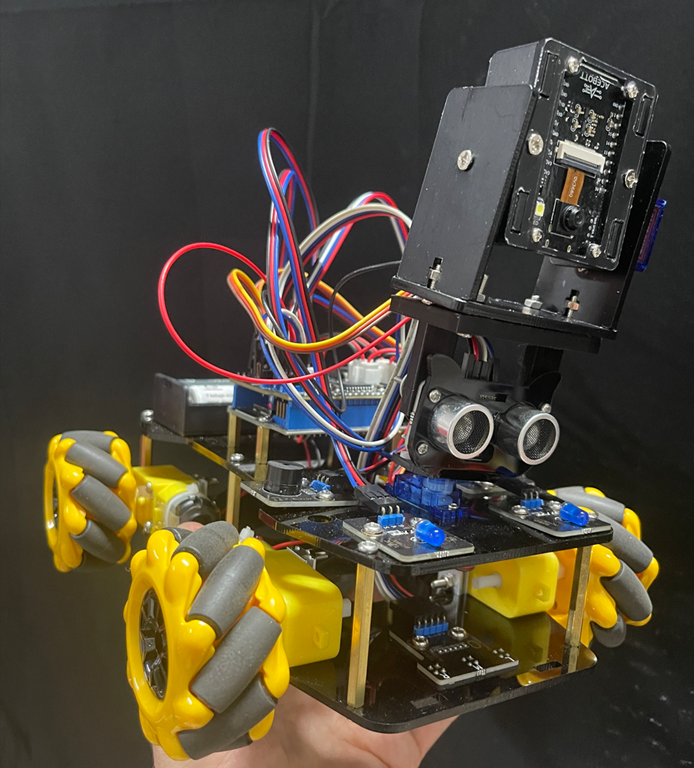
I’ve taken the standard ACEBOTT ESP32 Smart Car Starter Kit with Mecanum Wheels and added the ACEBOTT Bluetooth Controller Expansion for QD001 (QD010) to control its movement. I have also added the ACEBOTT ESP32 Camera Expansion pack for Smart Car (QD002) to give the car vision.

You can see that I have kept the ultrasonic sensor from QD001 and simply mounted the camera (QD002) on top to facilitate pan left and right. I could have added an additional servo to control this independently of the ultrasonic sensor, however in the end I decided that it was easier simply to print a 3D mount so the camera unit could sit above the ultrasonic senor and take advantage of the pan left and right servo already in place. I could refine the design with a separate 3D printed mount for the camera unit if desired, but for the sake of getting things working I’ve decide to stay with thsi method.

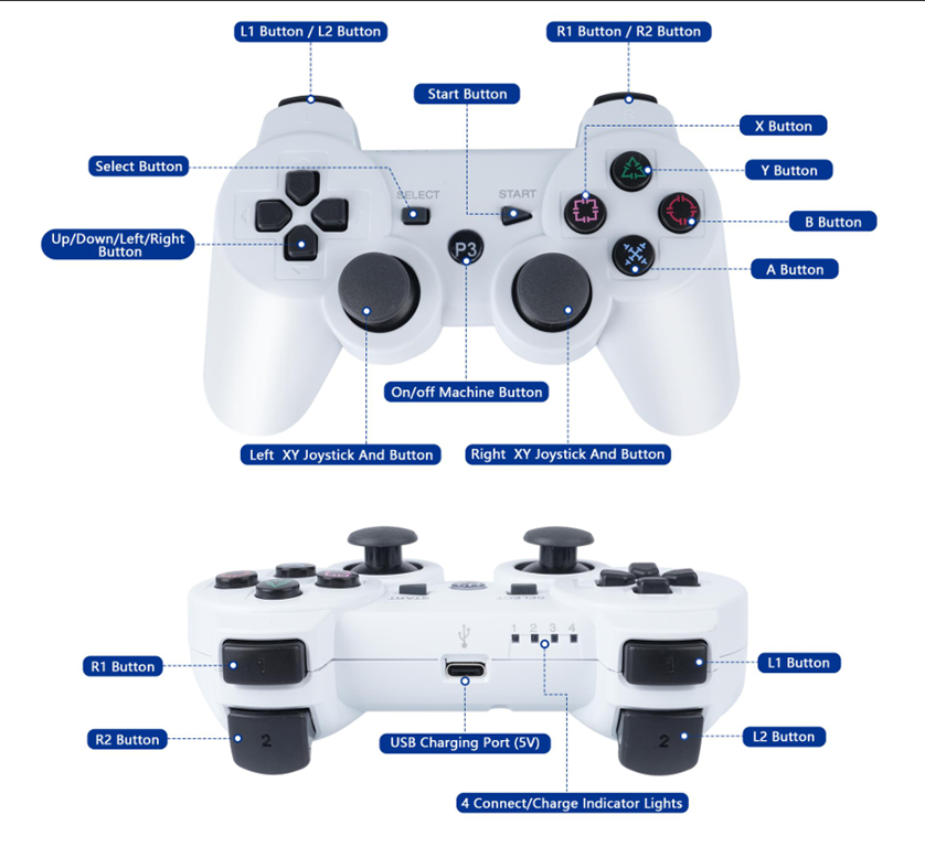
I have detailed how to get the PS3 controller (QD010) working with the robot car (QD001) here –

https://blog.ciaopslabs.com/2025/12/28/connecting-a-joystick-controller-to-an-acebott-esp32-smart-car/

and I have covered off getting the camera (QD002) working stand alone here:

https://blog.ciaopslabs.com/2025/12/31/connecting-a-webcam-to-an-acebott-esp32-smart-car/

You’ll find the code and documentation in those articles. At a minimum you’ll need to program the camera (QD002) to support the creation of a web server so it can stream the video to a device.

To mount a device with a screen (an old iPhone) to the PS3 controller (QD010) I found this:

Universal smartphone mount for DUALSHOCK 3 (PS3 controller)

that I could 3D print. I did need to slight extend the width of the base to suit my controller but it worked a treat.

Screenshot 2026-01-04 103123

The above version of the holder was my first printing attempt where I broke the lower part of the base holder when attempting to fit on the controller. This lead to me slightly lengthening the model the second time around that fixed the issue. The initial broken model is secured here using some rubber bands but the re done version fits perfectly.

With the code loaded into the robot car (QD001) and the camera (QD002) as well as having the PS3 controller (QD010) connected the end result looks like:

Connecting a webcam to an ACEBOTT ESP32 Smart Car

blog

With a PS3 style controller connected to an Acebott ESP32 Smart Car my next task was getting the add QD002 ACEBOTT ESP32 Camera Expansion pack for Smart Car working.

I had previously tried to get an Arducam Mega 3MP working and failed miserably, but was highly motivated to overcome that setback with a purpose built camera add on in the Acebott QD002.

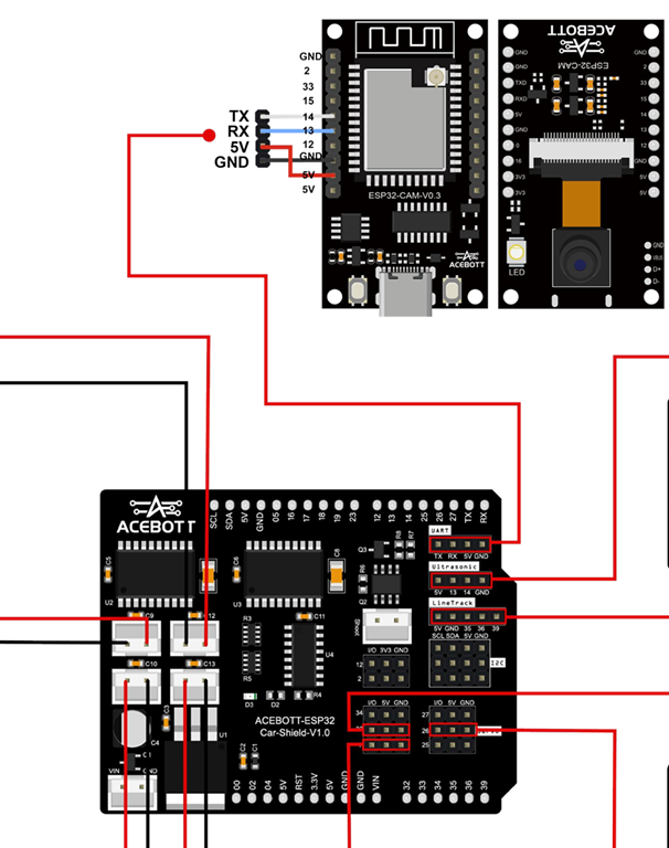
Things did not get off to a great start because the connection process required the camera to be connected to the UART port of the driver board.

Screenshot 2025-12-31 222556

The problem with that is the UART port conflicts with the serial port for uploads and monitoring. This mean hat I needed to disconnect the camera UART connection every time I wanted to update my code and then with it reconnected there was no real way to monitor the result. I either need to go to great lengths to program up and connected a different UART on the board or find another solution.

The easiest solution was to simply upload the code on the ESP32 camera to enable a web server to stream the code directly from the camera board. You’ll find that code here:

https://github.com/directorcia/Azure/blob/master/Iot/Acebott/Smartcar/QD002/ACEBOTT%20QD002%20Camera%20Car%20V3.8/webcam.cpp

and the documentation for it here:

https://github.com/directorcia/Azure/blob/master/Iot/Acebott/Smartcar/QD002/ACEBOTT%20QD002%20Camera%20Car%20V3.8/webcam.md

Thus, the camera board will boot, connect to WiFi, run a web server, report that IP address to the serial console of the web camera board and then stream the camera video there.

I cannot tell you how satisfying it was to finally seeing streamed images on my screen. It had taken a long time to to get here but now, finally, I was ready to finish assembly of the car and mount camera onto it!


Connecting a joystick controller to an ACEBOTT ESP32 Smart Car

blog

After being able to control the Acebott ESP32 Smart car via a web server my next aim was to control it using am Xbox/Playstation style joystick controller.

Initially I thought hat I could use an older Xbox style controller. Turns out these use 2.4Ghz wireless and a proprietary connection. Then I thought I could use a newer style Xbox controller that is Bluetooth, but it turns out they use Bluetooth 5 and use proprietary encryption. I did see a few of these working on the Internet but for the life of me I couldn’t get it to work.

I therefore asked AI which controller would be the easiest to get working and was told to get:

8BitDo Ultimate 2C Bluetooth Controller for Switch/Switch 2, Wireless Controller with 6-Axis Motion Control, Rumble Vibration, Refined D-Pad and Bumpers, and Hall Effect Joysticks (Blue)

This launched me into a world a hurt and failure (thanks AI). In short, this 8BitDo controller appears to also only be Bluetooth 5 and the Acebott ESP32 only supported Bluetooth 4.2 LE (Low Energy).

Making the same mistake twice (what’s the definition of stupidity again?) I asked AI to recommend a different ESP32 board that would work with the 8BitDo and was told that a “ESP32-C3 DevKit” would be the most reliable. I then went and bought an ESP32-C3 Mini Development Board. Even after being ‘100% sure’ that it would work, the AI could not make it work either.

I then came across the ACEBOTT Bluetooth Controller Expansion for QD001, which is designed for the Acebott Smart Car.

image

With this I finally could get the controller talking to the ESP32 on the Smart Car. However, to pair the controller and the ESP32 I needed to specific the MAC address of the controller, which is conveniently on the bottom of the controller. But to get the ESP32 to pair back to the controller I needed to embed the MAC address of the ESP32 Bluetooth connection into the controller. To do this it recommended using a Sixasix Pair tool. For the life of me, I couldn’t get this to work but with my Controller at least paired to the ESP32 I could send commands which is all I really wanted.

I got AI to rewrite the code to allow the PS3 style controller to control the movement of the SmartCar. I have uploaded the code here:

https://github.com/directorcia/Azure/blob/master/Iot/Acebott/Smartcar/QD010/car-ps3.cpp

I also needed to add some speed trimming of the motors because the car was veering off in one direction. The documentation for the above code is here:

https://github.com/directorcia/Azure/blob/master/Iot/Acebott/Smartcar/QD010/car-ps3-overview.md

This whole process proved much harder that I expected and getting a Bluetooth working initially as extremely frustrating given teh different versions and controllers, but now the ‘generic’ PS3 style controller works well!

ACEBOTT ESP32 Smart Car with IR Control

Screenshot 2025-08-28 080437

I got my ACEBOTT ESP32 Smart Car Starter Kit with Mecanum Wheel all wired and so the next challenge was to get it to move. Luckily, the kit comes with an Infra Red Remote control. I therefore wrote this code:

https://github.com/directorcia/Azure/blob/master/Iot/Acebott/Smartcar/irbuttonmap.cpp

To show me what all the buttons on the controller mapped to on the ESP32.

With that complete, I now wrote this code:

https://github.com/directorcia/Azure/blob/master/Iot/Acebott/Smartcar/irmovecontrol.cpp

to get the Smart Car to move by using the IR control. I documented the code here:

https://github.com/directorcia/Azure/blob/master/Iot/Acebott/Smartcar/irmovecontrol.md

The next step will be to run a small web server on the ESP32 and connect to that via local WIFI to move the car.

ACEBOTT ESP32 Smart Car Starter Kit with Mecanum Wheel

Screenshot 2025-08-28 080437

In my on going quest to get a camera working on a robot car and failing with an Arducam, I cam across an existing kit that has an add on extra of a camera. It is the:

ACEBOTT ESP32 Smart Car Starter Kit with Mecanum Wheel

with

ACEBOTT ESP32 Camera Expansion pack for Smart Car

which is going to make achieving my goal much, much easier.

To get the Smart car working you’ll need to nuy some batteries:

1 x CR2025 for the Infra Red Controller

2 x 18650 to the motors and controller board

Assembling the car is pretty straight forward and the kit give you a few spare items for those that you invariably drop on the floor and lose, which is nice. The main challenge I had was with the wiriing. It is always a good idea of take a photo of the components , both sides, BEFORE you assemble them so you can read the pin settings. Case in point, here is the Ultrasonic senor after I had to disassemble it to get the pin settings.

Screenshot 2025-08-28 081429

Hopefully, that saves someone else having to do same.

Here are some more I took of the motor shield board because reading the numbers for the connectors was challenging.

Screenshot 2025-08-28 081600

Screenshot 2025-08-28 081753

With everything finally assembled and powered up I wanted to wire some code to test all the sensors were working correctly. I used this for my tests:

https://github.com/directorcia/Azure/blob/master/Iot/Acebott/Smartcar/diag.cpp

It will flash the LEDs, move the servo for the ultrasonic sensor, test the IR receiver, play tunes on the buzzer and test all the wheels, forwards and backwards for you.

All teh driver files and the instructions can be downloaded here. This will give you everything you need for all the Smartcar kits and add ons.

My next step will be to code the Smartcar so that it moves in response to commands sent to it via the Infra Red controller. Stay tunes.