

Completed.
The next step in my plans was to add vision to my environment. For this I selected the Arducam Mega 3MP camera, which seemed to be straight forward enough from the initial research that I did. That has turned out to be significantly wrong.
I started off with trying to connect the camera to the ESP32 S2 Wroom but that was an abject failure. I then decided to move back to the Adafruit Huzzah ESP8266 to eliminate challenges with the ESP-32 S2 Wroom. Even this has proved challenging. Here’s what I have achieved so far.
The first challenge is to understand the SPI interface, which I haven’t dealt with before. You can read more about the SPI interface here:
https://docs.arduino.cc/learn/communication/spi/
and here:
https://learn.sparkfun.com/tutorials/serial-peripheral-interface-spi/all
but according to the docs:
Serial Peripheral Interface (SPI) is a synchronous serial data protocol used by microcontrollers for communicating with one or more peripheral devices quickly over short distances.
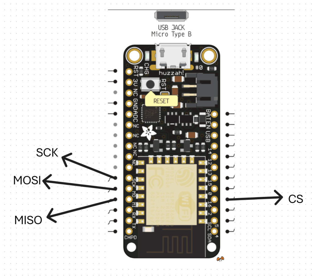
In essence, I needed to correct connect the Arducam Mega 3MP camera SPI interface to the Adafruit Huzzah ESP8266 SPI interface. The Arducam Mega 3MP camera pinouts look like:

and this is how I connected it to the Adafruit Huzzah ESP8266
1. CS (Chip Select) -> GPIO16 (or any available GPIO pin) (D4)
2. MOSI -> GPIO13 (D7)
3. MISO -> GPIO12 (D6)
4. SCK -> GPIO14 (D5)
5. GND -> GND
6. 3.3V –> 3V
VCC (3.3V) and GND for the camera I have taken from an external power supply source.
With all that now wired up, the other trick is that you need to have something to receive and display the image from the camera. All the demos I saw pointed to a Arducam GUI tool:
https://www.arducam.com/docs/arducam-mega/arducam-mega-getting-started/packs/GuiTool.html
or direct download:
https://github.com/ArduCAM/Arducam_Mega/releases/download/v2.0.1/ArducamMegaSetup_Windows_x64.exe
which you install on your PC and view the camera via the USB cable
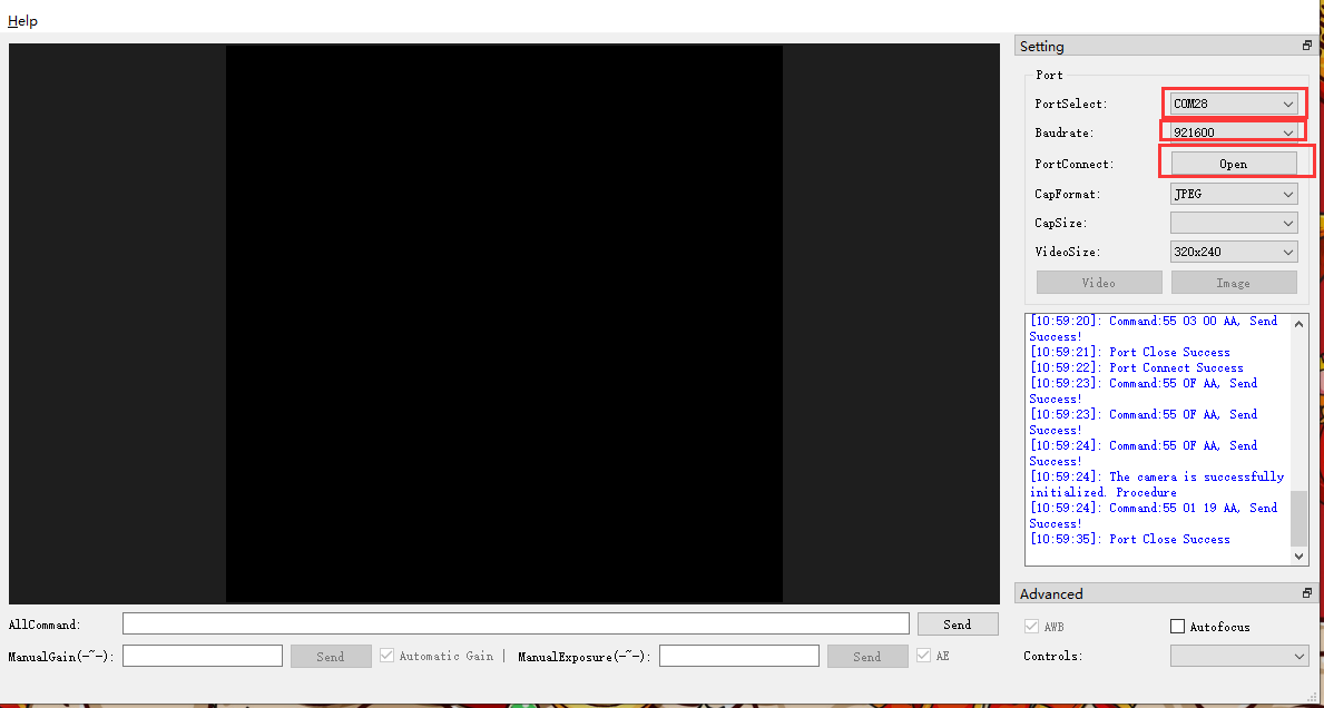
However, I had no real luck getting this to work at all with the example code provided. Therefore I returned to first principles.
I used this code:
https://github.com/directorcia/ciaopslabs/blob/main/Projects/15/ov3640-capture.cpp
to capture an image which seemed to work without any issues when I looked at the terminal messages and execution. Problem was, I could now capture an image but I couldn’t see it! I needed to send the image somewhere to view it. Rather than use the Windows app I thought I’d send it to an adafruit.io dashboard.
Once I had set up a dedicated feed in adafruit.io and a dashboard with an image widget I used this code:
https://github.com/directorcia/ciaopslabs/blob/main/Projects/15/ov3640-upload-v1.cpp
to try and send it. Unfortunately, I could see the code was executing and uploading to adafruit.io but I was getting feed errors. Some data had indeed appeared in the feed but an image wasn’t displaying. I also found that the Adafruit Huzzah ESP8266 was getting some sort of major error causing it to reset regularly.
After some investigation, it was recommended to disable the history on an adafruit.io feed to allow for greater data transfer sizes. The documentation tells me:
While history is turned ON, feed data is limited to 1KB (1024 bytes) in size.
While history is turned OFF, feed data is limited to 100KB (102400 bytes) in size

To do this go into the adafruit.io Feed and select the COG next to the Feed History heading as shown above. In the dialog that appears set the history to OFF as shown.
The other thing that I noted was:

The uploaded images appear to need to be base64 encoded.
I have some new code to try and overcome all of these issues which I’ll now go and try.

I’ve decided to upgrade the remote controller for the robot. Adafuit.io has the above component you can add to your dashboard. This provides a lot more commands than the original

one that I have been using as can be seen above.
My plan now is to add a pan and tilt camera to the robot so it can ‘see’. I’m also working on creating some additional parts for the robot to hold the 6V batter case as well as make the front platform more accessible. I’ll basically place it above the 6V battery which will sit over the front wheels.
I am also working on a way to better secure the bread board onto the robot rather than using a bulldog clip. It is all getting rather crowded up there, so creating some more space will be good.
It seems like the camera interfaces to the ESP32S2 Wroom using a set of SPI connectors which are:

which I found here:
https://docs.arducam.com/Arduino-SPI-camera/MEGA-SPI/MEGA-Quick-Start-Guide/
most of which I can see on the board:

The one that is missing is CS = 7. I found this after some hunting:
pin 7 on the ESP32-S2 Thing Plus WROOM is the IO4 pin
I am not sure whether it os true but I’ll try:

GPIO04 on the other side of the chip as shown above as the pin for CS.
I bought this camera:
https://core-electronics.com.au/arducam-mega-3mp-camera.html
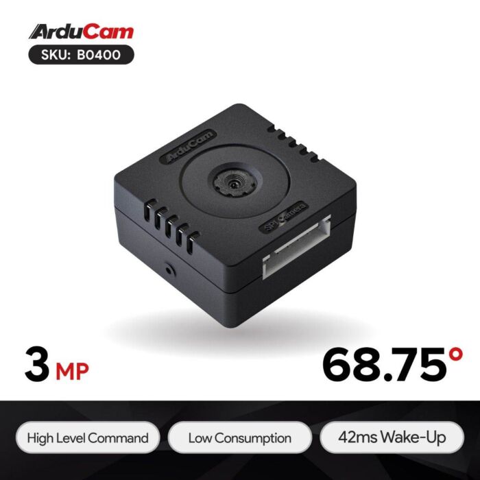
which has pinouts:

Once I get it all connected then I need to write to code to capture images. There are lots of examples of doing that with an app on your desktop but I want the camera to capture an image and send it up to adafuit.io which it seems I can do. No sure of exactly how just yet, but first step is getting the camera hooked up and being able to view the images it captures.
As I detailed in a previous post:
I had my robot moving and taking commands from an Internet based dashboard. The missing piece was to get the distance sensor operational, which I have now achieved.
I firstly need to print a mount to allow the distance sensor to be mounted to the buggy frame. I have uploaded that to the CIAOPSLabs repo here:
https://github.com/directorcia/ciaopslabs/blob/main/3dprint/mounts/VL53L0X-distance.stl

With the VL53L0X sensor now mounted and connected to the processor the layout now looked like the above image.
Basically, the motor controller, distance sensor and LCD display all communicate with the ESP32-S2 processor via the SDA/SCL bus. They achieve this by all being on a different address.
It was also important to ensure that I connected up the wheel in a know sequence because to drive the mecanum motion I needed to turn different wheels to make it move in certain directions per:
I’ve uploaded the initial code with it all working here:
https://github.com/directorcia/ciaopslabs/blob/main/Projects/14/moveanddistance-v1.c
The commands on the keyboard are:

1 = Left forward 45
2 = Forward
3 = Right forward 45
4 = Left 90
5 = Stop/Start
6 = Right 90
7 = Left back 45
8 = Back
9 = Right back 45
* = Slower
0 = Spin on the spot
# = Faster
As the robot moves it displays the distance on the LCD display like so:

The robot starts with speed = 0 (i.e. stationery). You press 5 to set the speed to 100 but it will not yet move until you give it a direction. If you now press 2, the robot will move forward at a speed of 100. You can then happy go along changing directions via the keypad. If you press 5 again, the robot will stop moving.
With all this now working, the next update will be for the robot to use the distance sensor to determine how far away it is from object (at the front), slow and stop if necessary to avoid hitting these objects.
I want to also optimise the code to make it more responsive if I can and I’ll post the updates here and to the CIAOPSLabs repo when I get it all working.
Beyond that I’m still trying to decide what to get the robot to do? If you have any suggestions, let me know but I’m kind of thinking that the robot needs to have ‘vision’ next!

I’ve been back printing more Gridfinity containers on my Snapmaker Artisan and have updated the times taken above.

Part of recent Mecanum motion project required me to design and print a frame for the DFRobot 1602 LCD display as shown above. It is basically a right angle bracket that allows it to be mounted onto the frame.
I’ve uploaded the STL model to:
https://github.com/directorcia/ciaopslabs/blob/main/3dprint/mounts/DFRobot-1602-LCD-disp.stl
so you can grab a copy and print it out for yourself. If you don’t have access to a 3D printer then send me a donation via:
to cover the postage at least and I’ll send you a print.

One the problems I’ve recently solved with 3D printing was to create a simple paint mixer (shown above).
Basically it is a block with a few divots in it. This allows you to easily a small amount of paint in each divot. The advantage over a flat area is that the mixing process doesn’t spread the paint too broadly. This solved a problem for me when I am building my plastic models and need a small amount of colours mixed together.
The dimensions of the mixer are:
76.8 mm long
19 mm wide
4.8 mm deep
I’ve uploaded the STL model here:
https://github.com/directorcia/ciaopslabs/blob/main/3dprint/tools/Paintmixer.stl
so you can grab a copy and print it out for yourself. If you don’t have access to a 3D printer then send me a donation via:
to cover the postage at least and I’ll send you a print.
https://www.youtube.com/watch?v=9vtnGbYjG7k
Happy to say that my robot frame is now able to move around as seen in the above video. I’ll post more details up soon once I make some small improvements but stoked to have it all working and controlled from my phone!

Hopefully you can see from the above video that I have now got all the wheels turning on the frame in the same direction.
With the motor basics done, next I’ll get the rig talking to WiFi and outputting information to the LCD display.
Following that, the next step is to determine how to move in different directions with these Mecanum wheels.

I’ve invested in a new chassis for my robot creations. This is the one I opted for:
from Amazon. It is great quality, strong and well made. Has lots of connection options and the right size for what I want. It is also robust enough to survive the inevitable ‘incidents’ it will no doubt have along the way. In short, I think it is great value for money and very professionally made.
As you can see from the above picture, I have managed to put it together, even though it didn’t come with assembly instructions. Those I found here:
https://www.hiwonder.com/products/mecanum-wheel-chassis-car
and specifically on this YouTube video – https://youtu.be/WMQ-PyM-PNE
The motor connections are JST 2-pin female connectors so I have also ordered these:
JST PH 2-Pin Cable – Male Header 200mm
to allow easy connection to the motor driver I’ve already played with here:
https://blog.ciaops.com/2023/07/12/iot-motors/
Once I get all that I can start putting together the controllers and then start writing the code to make it actually move about.
Stay tuned.
