Ferrari SF-24 F1 Car 42207 | Technic | Buy online at the Official LEGO® Shop AU
Author: directorcia
Fujimi 1/24 Ferrari F12 Berlinetta
Arduino Uno R4 Wifi Matrix display
The next controller I’m going to play with is the Arduino Uno R4 Wifi. I really like the ease and compatibility of the Arduinos I have used so far but the lack of WiFi I know will be a major limitation. So it make sense to explore a Wifi Uno.
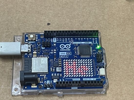
One of the additional ‘nice’ features of the Arduino Uno R4 Wifi is that it has a LED matrix included on the board. Thus, the starting point is to try and get something to display on there.
First I tried displaying a simple emjoi. The code for this is here:
and there are range of emojis to display.
I then uploaded the demo code here:
to display Hello World on the matrix, which all worked as expected as shown on the image above.
The next step after getting something to display on the matrix will be to get the Wifi working.
Garage distance sensor V2

My initial prototype started back here:
and is now at the point where I am designing version 2.
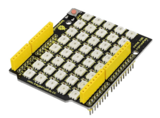
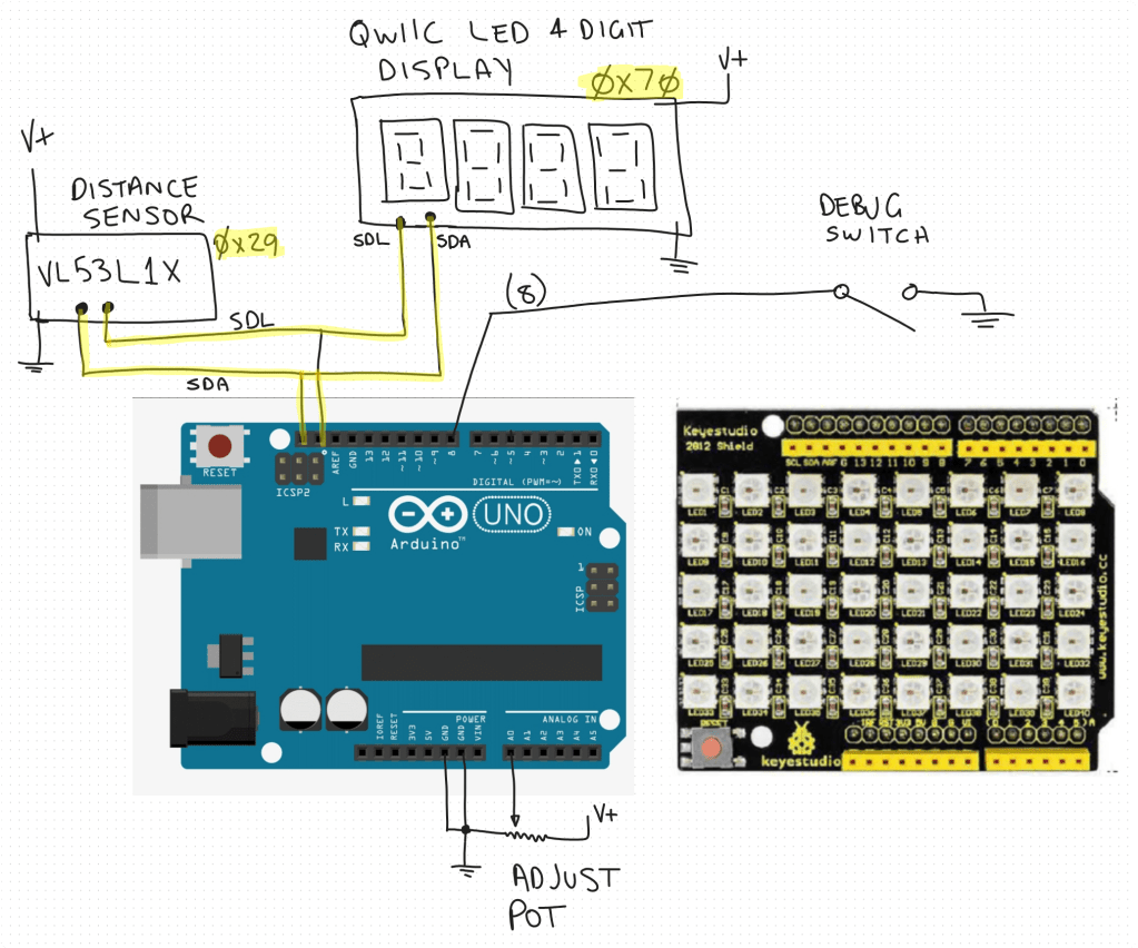
The biggest change for version 2 will be the replacement of the 5 individual LEDs and the board they live on with a Keyestudio 40 RGB LED WS2812 Pixel Matrix Shield for Arduino:

The main reasons for this are:
– less soldering is required
– the LEDs are brighter
– there will be a 5 x 8 matrix of LEDS allowing more options
– the shield plugs directly into the controller board
So the circuit diagram will now look like:

The code will, at least initially remain functionally the same but may get enhanced once I have it working.
I have ordered an additional distance sensor and QWIIC LED 4 Digit display but the LED shield is ready to go as you can see in this video:
Video link = https://www.youtube.com/watch?v=49V33TKXt3c
The test code shown in video is here:
I think this LED shield will be a big improvement for the project, so stay tuned for more updates soon.
Robot Arm with Multi Motor Movement
I’ve improved the movement of my robot arm by implementing multi motor movement. This means moving large distances will be more efficient since the arm can take a more direct route. You can see this in the video I created above. You’ll find my code for this routine here:
https://github.com/directorcia/Azure/blob/master/Iot/Arduino%20Uno%20R3/Robot%20Arm/routine2.cpp
This has lead me to go down the rabbit hole of kinematics.
Kinematics is the science of motion without considering forces. For robot arms, it answers questions like:
-
Where should each joint move to place the end-effector at a specific position?
-
What angle should each servo rotate to reach a target point?
There are two primary types:
-
Forward Kinematics – You provide joint angles, and it calculates the end-effector’s position.
-
Inverse Kinematics (IK) – You provide a desired end-effector position, and it calculates the joint angles needed to get there.
I’m going to try and implement kinematics for my arm going forward, so stay tuned for updates.
Keyestudio Sensor Shield/Expansion Board V5 for Arduino
One of the issues I found when powering the servos for the robot arm was that I found I couldn’t power them from the Arduino board, I needed an external power supply. This fact made wiring the servos up challenging as the control signal still had to come from the Arduino but the power elsewhere. Thus, lots of messy wires.
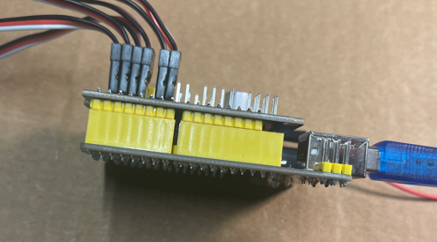
All that has been solved with the addition of a Keyestudio Sensor Shield/Expansion board as seen above.
Basically, the shield simply plugs into the pins in the Arduino controller (extending them) while providing:
– An alternate power supply
– Easy connections for all the servos
A nice compact solution to a few challenges with the robot arm. All I needed to do was connect up the shield onto the Arduino and then connect the servo motors directly to their ports and change nothing else. No code or other wiring was done except to also connect an external power supply to the shield board as seen in the lower right above.
I have to say, that if you need to control devices that require more power than the standard Arduino board can provide then this type of shield is exactly what you want!
Thumbs up to Keyestudio for both the controller:
KEYESTUDIO UNO R3 Development Board For Arduino Official Upgrated Version With Pin Header Interface
and the shield
Keyestudio Sensor Shield/Expansion Board V5 for Arduino
A diagram of the project looks like:
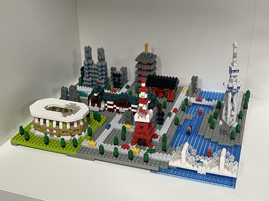
Nanoblock Tokyo Skyline Building Kit
Nanoblock Tokyo Skyline Building Kit, White – https://www.amazon.com.au/Nanoblock-Tokyo-Skyline-Building-White/dp/B07CDQQXWG/
1310 pieces
A kit with a lot of different components and colours. Takes longer to assemble than you think simply because you need to find a lot of unique pieces. However, enjoyed the longer assembly process and overall details of the end result. If you don’t mind so many unique pieces then this is great longer term build of intermediate difficulty.
Garage sensor–Version 1 summary
![]()
Video link = https://www.youtube.com/watch?v=MBYtc1O-l94
I’ve rounded off version 1 of the Garage sensor and am about to start work on version 2. There is a short video summary of what he sensor does in the video above.
I’m not happy with the daughter board that runs the 5 LEDs. It is cumbersome, challenging and time consuming to build. I plan to replace this with something pre-built. I’ll also opt for a cheaper Arduino board. The process will also require me to rework the 3D printed board all the components are mounted on.
Stay tuned for Version 2 coming soon!
Robot arm in action–Linear motion
Video link = https://www.youtube.com/watch?v=zdtojnnbCBg
Now that I have my robot arm actually working, I can share the video of its operation above. It basically operates one servo at time to pick up and object and then place that object to the left. It will simply continue to do that over and over.
The code for this is here:
https://github.com/directorcia/Azure/blob/master/Iot/Arduino%20Uno%20R3/Robot%20Arm/routine1.cpp
Which I’ll explain in an upcoming post soon.
After that I want to modify the operation so that it more more naturally and operates multiple servos together to arrive at its destination.
Getting the robot arm to actually work
After taking a good while to get the robot arm assembled, the next challenge was hooking it up and doing some initial testing.
To control the arm I had invested in a
KEYESTUDIO UNO R3 Development Board For Arduino Official Upgrated Version With Pin Header Interface
This is the same board that is used on the Sun follower kit I recently built. I like this board because it has all the connections for each port already mounted on the board. It also has the GND and VCC for each port as well making it easy to plug standard connectors into it. Less soldering, in my case , means less problems or stuff ups by me!
The first issue I discovered was that many of the leads to the servos were too short when the servo moves the arm through its full motion. In one case I threw the controller board off the table. Thus I needed to invest in:
and
to allow full movement of the arm.
The next challenge I found was when I moved on from testing each servo individually to testing the arm as single unit, some of the servos didn’t seem to work! Another oversight by me upon further investigation. The controller board has enough power to run a single servo but not a bank of servos all together from the VCC rails on the controller board.
I therefore connected the VCC of the all the servos directly to my bench top power supply to give it the juice needed. Interestingly, during testing I have seen the arm draw well over 1 amp in total from the power supply as various servos operate. Clearly, no way the controller board could provide that by itself.
With all the servo motors now working, I started to try and get the arm to move to a location and pick up an item. After a while, servo 0 (gripper) stopped working?? I checked all the connections and it still wasn’t working. It wasn’t until I actually touched the servo and found that it was super hot that I realised I must have burnt it out. Damm.
I replaced the burnt out servo with another I had. I also attempted to fix the burnt out servo by opening it up to see if I could free things up inside, but that didn’t go well and I ended up with the internals of the servo motor all over the floor.
I also learnt that when power is removed from the servos, for example when re-flashing the controller board, the servos don’t hold the arm in place. This means that when power is removed from the servos the arm collapses under its own weight. This can cause some unexpected impacts with the environment when power is restored. I’ll need to think about how to solve this down the track but for now I simply support the arm when I flash the controller with updated code.
Finally, with a replacement servo for the gripper and motor extension cables I had the arm operational to a point where I could start getting it to do something interesting.
I’ll cover off the code development in an upcoming article and hopefully also provide some videos of the arm in operation.