When I tried to use a generic DHT sensor library from the Platformio registry for the project wouldn’t work. I therefore needed to work out how to use thr provide library with Platformio. Turns out that is much easier than I thought!
Inside your PlatformIO project, navigate to the lib/ directory.
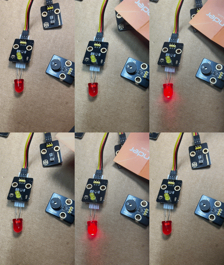
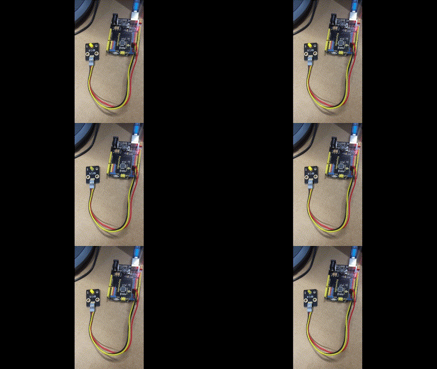
During this process the LED on the add on board failed! Strange. I checked the port, the voltage and whole lot of other stuff, but as far as I can tell the LED itself failed! I therefore used the buzzer as substitute until I decided to ‘bodgy’ another LED I had laying around as a temporary substitute. Why? Well, this LED board is pretty handy for troubleshooting I’ve found.
The result is as shown above, both sound and light when the light sensor falls below a certain level.
I can’t find a replacement for the LED board on its own. Seems it only comes with full kits. I’ll need to look at buying a similar LED at some stage and maybe swapping the faulty on out on the board. It will be rather fiddly but worth the effort going forward I reckon.
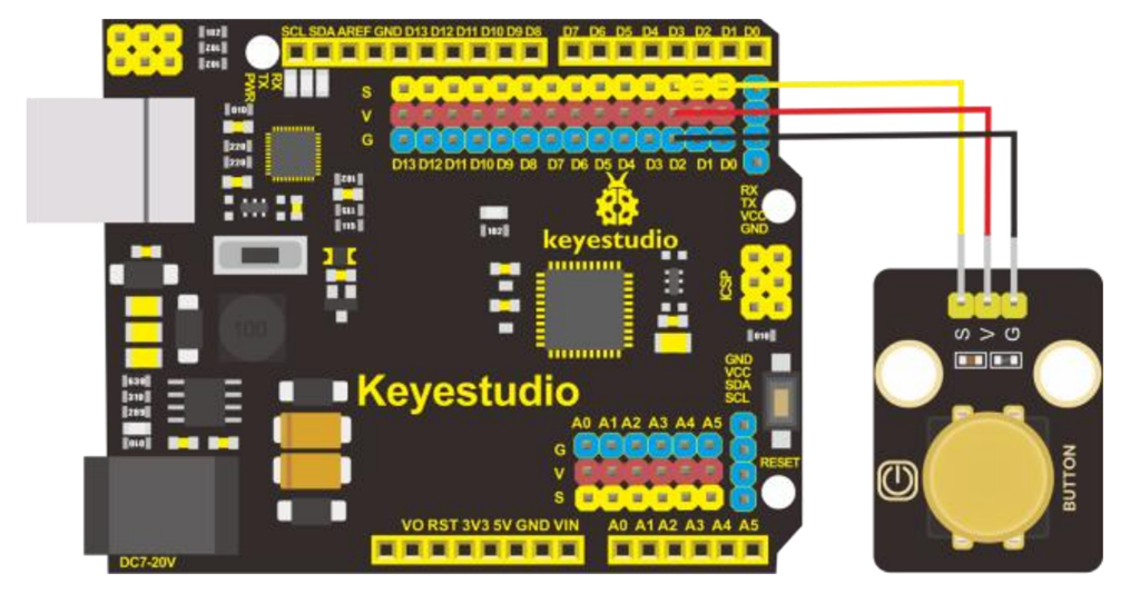
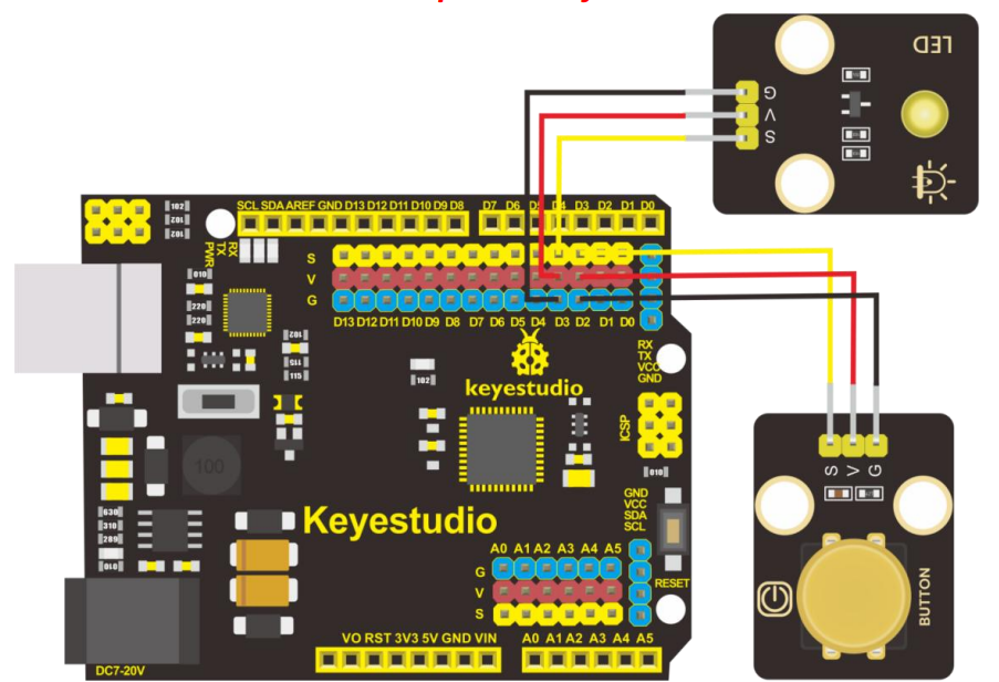
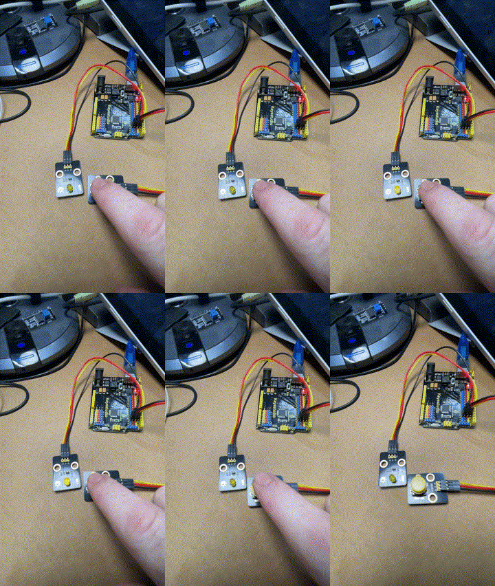
The next project with the Keyestudio KS0172 board is to connect a button as shown above and observe the effect in the terminal window. The code for this is here:
The analogWrite function is used in Arduino programming to output a PWM (Pulse Width Modulation) signal to a specified pin. Here’s a detailed explanation:
Purpose
analogWrite is used to control the brightness of an LED or the speed of a motor by varying the duty cycle of the PWM signal.
Syntax
analogWrite(pin, value);
Parameters
pin: The pin number to which the PWM signal is sent. This must be a pin that supports PWM (usually marked with a ~ on Arduino boards).
value: The duty cycle of the PWM signal. It ranges from 0 to 255:
0 means 0% duty cycle (always off).
255 means 100% duty cycle (always on).
Values in between correspond to varying levels of on/off time.
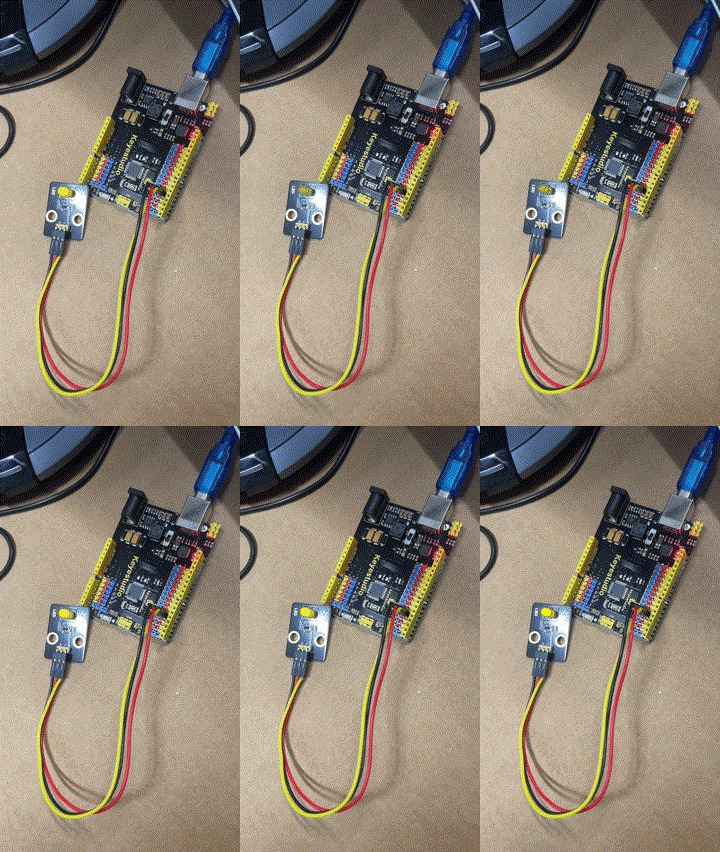
This code creates a smooth fade-in and fade-out effect for the LED.
Which I thought would be a good opportunity to jump back into things after all teh struggles I’ve had with the Arducam Mega 3MP. I need a few wins to lift my motivation, thus the purchase.
The brains of the kit is a Keyestudio KS0172:
The core processor of this board is ATMEGA328P-AU and ATMEGA16U2 is used as a UART-to-USB conversion chip.
It has 14 digital input/output pins (of which 6 can be used as PWM outputs), 6 analog inputs, a 16MHz crystal oscillator, a USB connection, a powerjack, 1 ICSP header, and a reset button. All you need to do is connect it to a computer via a USB cable and power it with an external power supply of DC 7-12V
Which seems much easier to interface.
Turns out this kit is actually a series of projects with the board, which is exactly what I wanted. Start simple and then extend.
First step was to get the board working with Platformio environment.
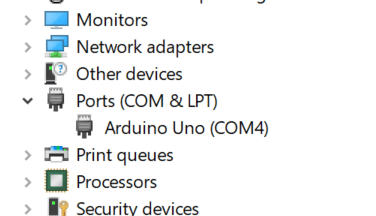
When I plugged the board into my PC it was automatically recognised as Arduino Uno as see above. Thus, when I set up Platformio I select Arduino Uno. This produced the following platformio.ini for me:
[env:uno] platform = atmelavr board = uno framework = arduino
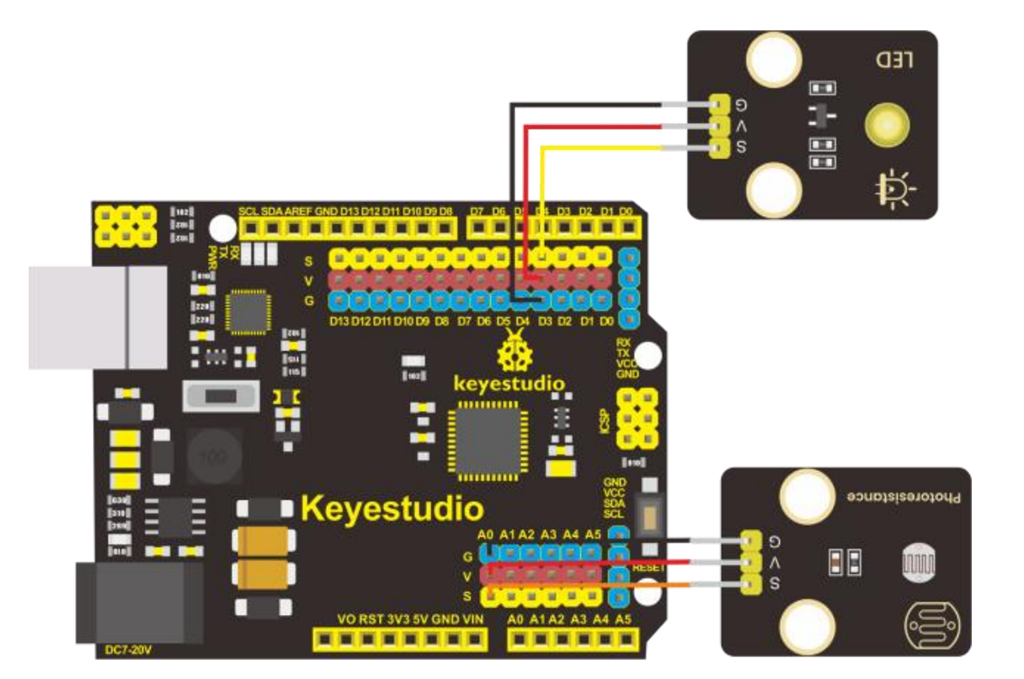
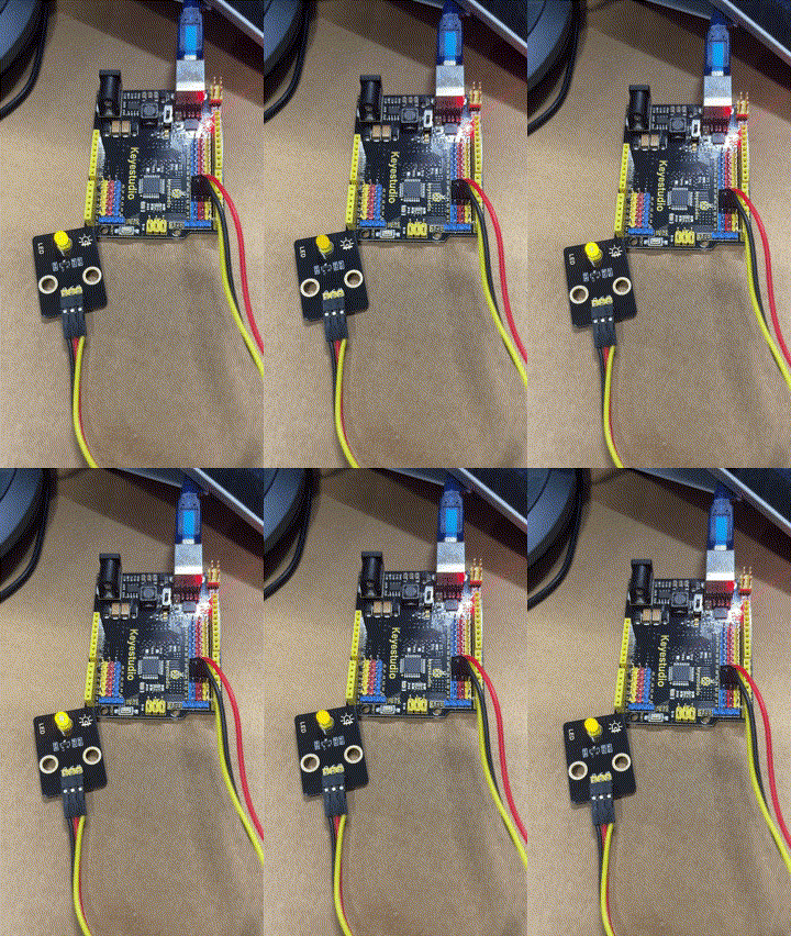
I then wired up the LED board per the instructions in the manual like so:
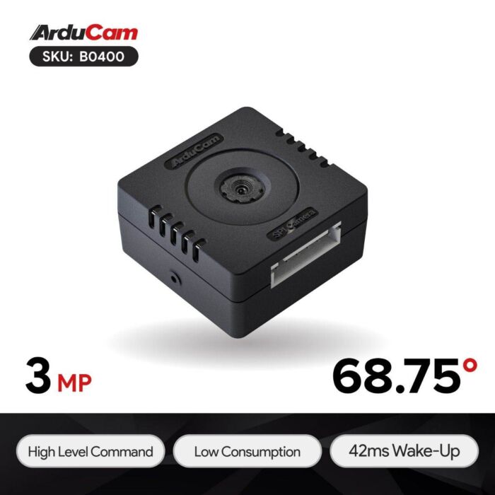
The next step in my plans was to add vision to my environment. For this I selected the Arducam Mega 3MP camera, which seemed to be straight forward enough from the initial research that I did. That has turned out to be significantly wrong.
I started off with trying to connect the camera to the ESP32 S2 Wroom but that was an abject failure. I then decided to move back to the Adafruit Huzzah ESP8266 to eliminate challenges with the ESP-32 S2 Wroom. Even this has proved challenging. Here’s what I have achieved so far.
The first challenge is to understand the SPI interface, which I haven’t dealt with before. You can read more about the SPI interface here:
Serial Peripheral Interface (SPI) is a synchronous serial data protocol used by microcontrollers for communicating with one or more peripheral devices quickly over short distances.
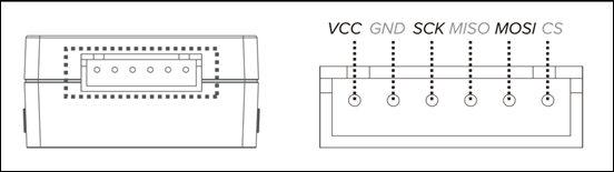
In essence, I needed to correct connect the Arducam Mega 3MP camera SPI interface to the Adafruit Huzzah ESP8266 SPI interface. The Arducam Mega 3MP camera pinouts look like:
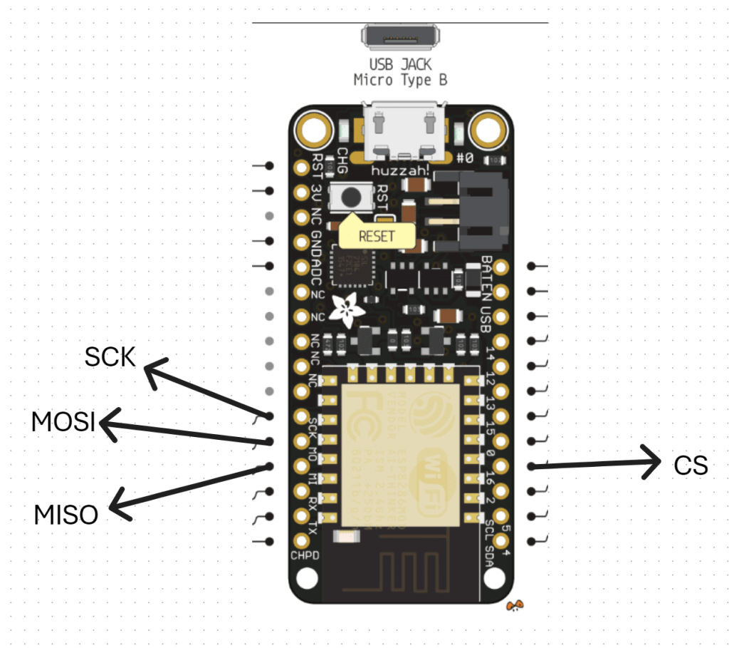
and this is how I connected it to the Adafruit Huzzah ESP8266
1. CS (Chip Select) -> GPIO16 (or any available GPIO pin) (D4)
2. MOSI -> GPIO13 (D7)
3. MISO -> GPIO12 (D6)
4. SCK -> GPIO14 (D5)
5. GND -> GND
6. 3.3V –> 3V
VCC (3.3V) and GND for the camera I have taken from an external power supply source.
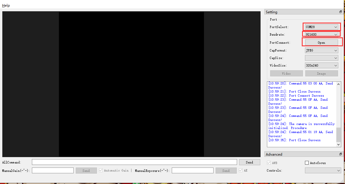
With all that now wired up, the other trick is that you need to have something to receive and display the image from the camera. All the demos I saw pointed to a Arducam GUI tool:
to capture an image which seemed to work without any issues when I looked at the terminal messages and execution. Problem was, I could now capture an image but I couldn’t see it! I needed to send the image somewhere to view it. Rather than use the Windows app I thought I’d send it to an adafruit.io dashboard.
Once I had set up a dedicated feed in adafruit.io and a dashboard with an image widget I used this code:
to try and send it. Unfortunately, I could see the code was executing and uploading to adafruit.io but I was getting feed errors. Some data had indeed appeared in the feed but an image wasn’t displaying. I also found that the Adafruit Huzzah ESP8266 was getting some sort of major error causing it to reset regularly.
After some investigation, it was recommended to disable the history on an adafruit.io feed to allow for greater data transfer sizes. The documentation tells me:
While history is turned ON, feed data is limited to 1KB (1024 bytes) in size.
While history is turned OFF, feed data is limited to 100KB (102400 bytes) in size
To do this go into the adafruit.io Feed and select the COG next to the Feed History heading as shown above. In the dialog that appears set the history to OFF as shown.
The other thing that I noted was:
The uploaded images appear to need to be base64 encoded.
I have some new code to try and overcome all of these issues which I’ll now go and try.
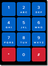
I’ve decided to upgrade the remote controller for the robot. Adafuit.io has the above component you can add to your dashboard. This provides a lot more commands than the original
one that I have been using as can be seen above.
My plan now is to add a pan and tilt camera to the robot so it can ‘see’. I’m also working on creating some additional parts for the robot to hold the 6V batter case as well as make the front platform more accessible. I’ll basically place it above the 6V battery which will sit over the front wheels.
I am also working on a way to better secure the bread board onto the robot rather than using a bulldog clip. It is all getting rather crowded up there, so creating some more space will be good.
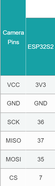
It seems like the camera interfaces to the ESP32S2 Wroom using a set of SPI connectors which are:
Once I get it all connected then I need to write to code to capture images. There are lots of examples of doing that with an app on your desktop but I want the camera to capture an image and send it up to adafuit.io which it seems I can do. No sure of exactly how just yet, but first step is getting the camera hooked up and being able to view the images it captures.
I had my robot moving and taking commands from an Internet based dashboard. The missing piece was to get the distance sensor operational, which I have now achieved.
I firstly need to print a mount to allow the distance sensor to be mounted to the buggy frame. I have uploaded that to the CIAOPSLabs repo here:
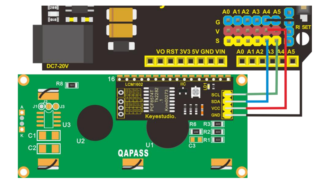
With the VL53L0X sensor now mounted and connected to the processor the layout now looked like the above image.
Basically, the motor controller, distance sensor and LCD display all communicate with the ESP32-S2 processor via the SDA/SCL bus. They achieve this by all being on a different address.
It was also important to ensure that I connected up the wheel in a know sequence because to drive the mecanum motion I needed to turn different wheels to make it move in certain directions per:
I’ve uploaded the initial code with it all working here:
As the robot moves it displays the distance on the LCD display like so:
The robot starts with speed = 0 (i.e. stationery). You press 5 to set the speed to 100 but it will not yet move until you give it a direction. If you now press 2, the robot will move forward at a speed of 100. You can then happy go along changing directions via the keypad. If you press 5 again, the robot will stop moving.
With all this now working, the next update will be for the robot to use the distance sensor to determine how far away it is from object (at the front), slow and stop if necessary to avoid hitting these objects.
I want to also optimise the code to make it more responsive if I can and I’ll post the updates here and to the CIAOPSLabs repo when I get it all working.
Beyond that I’m still trying to decide what to get the robot to do? If you have any suggestions, let me know but I’m kind of thinking that the robot needs to have ‘vision’ next!
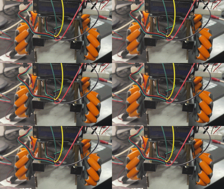
Happy to say that my robot frame is now able to move around as seen in the above video. I’ll post more details up soon once I make some small improvements but stoked to have it all working and controlled from my phone!