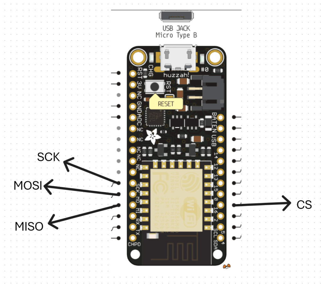
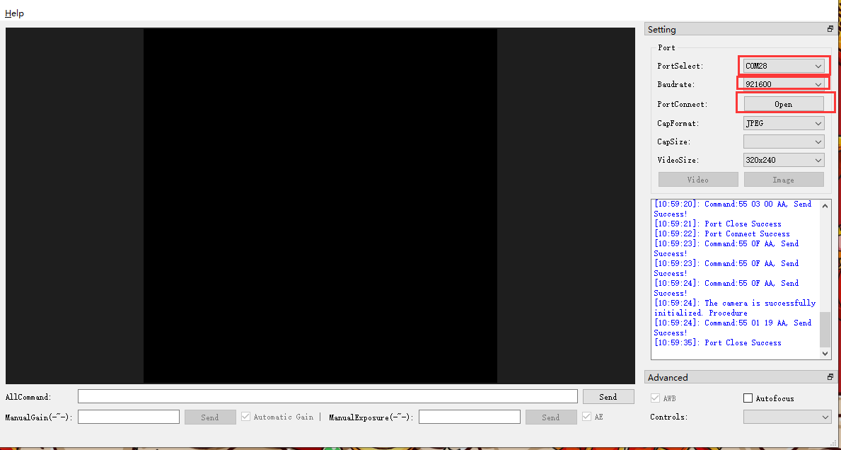
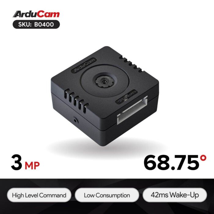
Arducam as a live web cam

blog1

I recently managed to Send images from Arducam to Azure, which was a major win. Only challenge with that is it isn’t easy to see those images inside Azure. Thus, I wanted an easy way to do this and figured that displaying on a web page was the go.

Turns out, this isn’t to hard using Azure. Thus, I started by modifying the code for the controller so it would always upload an image using the same name and do so every 60 seconds. You can find the code for the controller here:

https://github.com/directorcia/Azure/blob/master/Iot/Arducam/3MP/storage-web.cpp

and documentation here:

https://github.com/directorcia/Azure/blob/master/Iot/Arducam/3MP/storage-web.md

Next, I created an index.html file to display the image from Azure Blob storage. You can find a copy of that here:

https://github.com/directorcia/Azure/blob/master/Iot/Arducam/3MP/web-index.html

you need to rename it to index.html and put the name of your Blob storage URL on line 40.

Next, you’ll need to enable a static website on your Blob storage account.

image

  1. Go to Azure Portal (portal.azure.com)
  2. Navigate to your storage account: arducamimages
  3. In the left menu, find “Static website” (under “Data management” or “Settings”)
  4. Click “Enabled”
  5. Set Index document name: index.html
  6. Note the Primary endpoint URL (e.g., https://arducamimages.z8.web.core.windows.net/)
  7. Click “Save”

image

Then you’ll need to upload your index.html to the $web container in your Blob storage account.

  1. In your storage account, click “Containers” (under “Data storage”)
  2. Click on the $web container (created automatically when you enabled static website)
  3. Click “Upload”
  4. Select your index.html file
  5. Check “Overwrite if files already exist”
  6. Click “Upload”

image

Now you’ll need to set public access for $web container.

  1. While in the $web container, click “Change access level”
  2. Set “Public access level” to “Blob (anonymous read access for blobs only)”
  3. Click “OK”

image

Next, set public access for images container

  1. Go back to “Containers”
  2. Click on the “images” container (where your latest.jpg is stored)
  3. Click “Change access level”
  4. Set “Public access level” to “Blob (anonymous read access for blobs only)”
  5. Click “OK”

image

You should be able to view the website using the Primary endpoint, that was back in the Static website settings as shown above. In my case I also need to add /index.html to end of the URL to get it to display.

image

You can see my result above. The page should refresh every 60 seconds automatically with a new image. You should also be able to now view this image from anywhere by simply browsing to your URL.

My next plan is to try and integrate Azure AI vision, given the image is already now in Azure, and for the page to report the weather i.e. sunny, wet, etc. yes, I know you can see that in the image but that makes it an easy way to very that Ai reading the image correctly. Let’s see how hard that is to do next.

ACEBOTT Smart car – Bringing it all together

blog

It is now time to bring all the pieces together on the Acebott Smart Car and make it a movable platform that can stream live video.

Screenshot 2026-01-04 101028

Screenshot 2026-01-04 101245

I’ve taken the standard ACEBOTT ESP32 Smart Car Starter Kit with Mecanum Wheels and added the ACEBOTT Bluetooth Controller Expansion for QD001 (QD010) to control its movement. I have also added the ACEBOTT ESP32 Camera Expansion pack for Smart Car (QD002) to give the car vision.

You can see that I have kept the ultrasonic sensor from QD001 and simply mounted the camera (QD002) on top to facilitate pan left and right. I could have added an additional servo to control this independently of the ultrasonic sensor, however in the end I decided that it was easier simply to print a 3D mount so the camera unit could sit above the ultrasonic senor and take advantage of the pan left and right servo already in place. I could refine the design with a separate 3D printed mount for the camera unit if desired, but for the sake of getting things working I’ve decide to stay with thsi method.

I have detailed how to get the PS3 controller (QD010) working with the robot car (QD001) here –

https://blog.ciaopslabs.com/2025/12/28/connecting-a-joystick-controller-to-an-acebott-esp32-smart-car/

and I have covered off getting the camera (QD002) working stand alone here:

https://blog.ciaopslabs.com/2025/12/31/connecting-a-webcam-to-an-acebott-esp32-smart-car/

You’ll find the code and documentation in those articles. At a minimum you’ll need to program the camera (QD002) to support the creation of a web server so it can stream the video to a device.

To mount a device with a screen (an old iPhone) to the PS3 controller (QD010) I found this:

Universal smartphone mount for DUALSHOCK 3 (PS3 controller)

that I could 3D print. I did need to slight extend the width of the base to suit my controller but it worked a treat.

Screenshot 2026-01-04 103123

The above version of the holder was my first printing attempt where I broke the lower part of the base holder when attempting to fit on the controller. This lead to me slightly lengthening the model the second time around that fixed the issue. The initial broken model is secured here using some rubber bands but the re done version fits perfectly.

With the code loaded into the robot car (QD001) and the camera (QD002) as well as having the PS3 controller (QD010) connected the end result looks like:

Connecting a webcam to an ACEBOTT ESP32 Smart Car

blog

With a PS3 style controller connected to an Acebott ESP32 Smart Car my next task was getting the add QD002 ACEBOTT ESP32 Camera Expansion pack for Smart Car working.

I had previously tried to get an Arducam Mega 3MP working and failed miserably, but was highly motivated to overcome that setback with a purpose built camera add on in the Acebott QD002.

Things did not get off to a great start because the connection process required the camera to be connected to the UART port of the driver board.

Screenshot 2025-12-31 222556

The problem with that is the UART port conflicts with the serial port for uploads and monitoring. This mean hat I needed to disconnect the camera UART connection every time I wanted to update my code and then with it reconnected there was no real way to monitor the result. I either need to go to great lengths to program up and connected a different UART on the board or find another solution.

The easiest solution was to simply upload the code on the ESP32 camera to enable a web server to stream the code directly from the camera board. You’ll find that code here:

https://github.com/directorcia/Azure/blob/master/Iot/Acebott/Smartcar/QD002/ACEBOTT%20QD002%20Camera%20Car%20V3.8/webcam.cpp

and the documentation for it here:

https://github.com/directorcia/Azure/blob/master/Iot/Acebott/Smartcar/QD002/ACEBOTT%20QD002%20Camera%20Car%20V3.8/webcam.md

Thus, the camera board will boot, connect to WiFi, run a web server, report that IP address to the serial console of the web camera board and then stream the camera video there.

I cannot tell you how satisfying it was to finally seeing streamed images on my screen. It had taken a long time to to get here but now, finally, I was ready to finish assembly of the car and mount camera onto it!


Configuring an Arducam Mega 3MP

The next step in my plans was to add vision to my environment. For this I selected the Arducam Mega 3MP camera, which seemed to be straight forward enough from the initial research that I did. That has turned out to be significantly wrong.

I started off with trying to connect the camera to the ESP32 S2 Wroom but that was an abject failure. I then decided to move back to the Adafruit Huzzah ESP8266 to eliminate challenges with the ESP-32 S2 Wroom. Even this has proved challenging. Here’s what I have achieved so far.

The first challenge is to understand the SPI interface, which I haven’t dealt with before. You can read more about the SPI interface here:

https://docs.arduino.cc/learn/communication/spi/

and here:

https://learn.sparkfun.com/tutorials/serial-peripheral-interface-spi/all

but according to the docs:

Serial Peripheral Interface (SPI) is a synchronous serial data protocol used by microcontrollers for communicating with one or more peripheral devices quickly over short distances.

In essence, I needed to correct connect the Arducam Mega 3MP camera SPI interface to the Adafruit Huzzah ESP8266 SPI interface. The Arducam Mega 3MP camera pinouts look like:

and this is how I connected it to the Adafruit Huzzah ESP8266

1. CS (Chip Select) -> GPIO16 (or any available GPIO pin) (D4)

2. MOSI -> GPIO13 (D7)

3. MISO -> GPIO12 (D6)

4. SCK -> GPIO14 (D5)

5. GND -> GND

6. 3.3V –> 3V

VCC (3.3V) and GND for the camera I have taken from an external power supply source.

With all that now wired up, the other trick is that you need to have something to receive and display the image from the camera. All the demos I saw pointed to a Arducam GUI tool:

https://www.arducam.com/docs/arducam-mega/arducam-mega-getting-started/packs/GuiTool.html

or direct download:

https://github.com/ArduCAM/Arducam_Mega/releases/download/v2.0.1/ArducamMegaSetup_Windows_x64.exe

which you install on your PC and view the camera via the USB cable

../_images/open.bmp

However, I had no real luck getting this to work at all with the example code provided. Therefore I returned to first principles.

I used this code:

https://github.com/directorcia/ciaopslabs/blob/main/Projects/15/ov3640-capture.cpp

to capture an image which seemed to work without any issues when I looked at the terminal messages and execution. Problem was, I could now capture an image but I couldn’t see it! I needed to send the image somewhere to view it. Rather than use the Windows app I thought I’d send it to an adafruit.io dashboard.

Once I had set up a dedicated feed in adafruit.io and a dashboard with an image widget I used this code:

https://github.com/directorcia/ciaopslabs/blob/main/Projects/15/ov3640-upload-v1.cpp

to try and send it. Unfortunately, I could see the code was executing and uploading to adafruit.io but I was getting feed errors. Some data had indeed appeared in the feed but an image wasn’t displaying. I also found that the Adafruit Huzzah ESP8266 was getting some sort of major error causing it to reset regularly.

After some investigation, it was recommended to disable the history on an adafruit.io feed to allow for greater data transfer sizes. The documentation tells me:

While history is turned ON, feed data is limited to 1KB (1024 bytes) in size.

While history is turned OFF, feed data is limited to 100KB (102400 bytes) in size

To do this go into the adafruit.io Feed and select the COG next to the Feed History heading as shown above. In the dialog that appears set the history to OFF as shown.

The other thing that I noted was:

The uploaded images appear to need to be base64 encoded.

I have some new code to try and overcome all of these issues which I’ll now go and try.

Controller upgrade

image

I’ve decided to upgrade the remote controller for the robot. Adafuit.io has the above component you can add to your dashboard. This provides a lot more commands than the original

image

one that I have been using as can be seen above.

My plan now is to add a pan and tilt camera to the robot so it can ‘see’. I’m also working on creating some additional parts for the robot to hold the 6V batter case as well as make the front platform more accessible. I’ll basically place it above the 6V battery which will sit over the front wheels.

I am also working on a way to better secure the bread board onto the robot rather than using a bulldog clip. It is all getting rather crowded up there, so creating some more space will be good.

It seems like the camera interfaces to the ESP32S2 Wroom using a set of SPI connectors which are:

image

which I found here:

https://docs.arducam.com/Arduino-SPI-camera/MEGA-SPI/MEGA-Quick-Start-Guide/

most of which I can see on the board:

image

The one that is missing is CS = 7. I found this after some hunting:

pin 7 on the ESP32-S2 Thing Plus WROOM is the IO4 pin

I am not sure whether it os true but I’ll try:

image

GPIO04 on the other side of the chip as shown above as the pin for CS.

I bought this camera:

https://core-electronics.com.au/arducam-mega-3mp-camera.html

AC-B0400-5

which has pinouts:

image

Once I get it all connected then I need to write to code to capture images. There are lots of examples of doing that with an app on your desktop but I want the camera to capture an image and send it up to adafuit.io which it seems I can do. No sure of exactly how just yet, but first step is getting the camera hooked up and being able to view the images it captures.