A while back I got the chassis with the mecanum wheels being controlled by an adafruit.io dashboard. I have revamped the controller to now be an Arduino Uno R4 WiFi controller with an Adafruit MotorShield V3, once again controller by an adafruit.io dashboard.
to test all the motors. The results of this are shown in the video at the top.
Using the ‘vibe’ coding and with thanks to Github Copilot, getting the results I wanted was really easy. It even installed the Adafuit_Motorshield drivers for me as well.
Now I know the shield works along with the all the motors. The next was to be to get the DFRobot 1602 LCD display working on teh Arduino Uno R4 Wifi. It was then I realised that I should have used the:
as I now didn’t have an easy way to connect the display. Damm! I’ll need to figure something else out to get the display working with the board. However, I am very pleased that the Adafruit Motor/Stepper/Servo Shield for Arduino v2 Kit – v2.3 works well and all the motors on my chassis are all operational again. I am now back to where I was with the S32 controller over a year ago.
If you haven’t worked out yet, I’m trying to get back to this point:
and as you can see from the video is now working. Thus, when I push a number on the Adafruit.io dashboard it is communicated down to the Arduino Uno R4 and displayed on the matrix.
The interesting thing is that I ma now ‘vibe’ coding solutions with Github Copilot. This means I am not writing the code by hand any more. I tell Copilot what I want it to so and allow it to generate the code for me. This saves me SO MUCH time as I am not an experienced C developer and all I want is to get my project working as fast as possible.
However, this ‘vibe’ coding approach still presents challenges. When I started out with thsi project the code Copilot developed for me used a HTTP connect to Adafruit.io dashboard which ended up being far too slow. I didn’t notice that fact unit a little ways into this. At that pont I had Copilot redo the code and only use MQTT, whcih now works athe speed expected.
‘Vibe’ coding is such a time saver for me with these projects and help me sort out issues faster that I could without it. However, the lesson here is that you need to understand what you are trying to achieve and help the AI understand as well.
The secret is to include the WiFiS3.h, which the wifi library for the R4. Aside from that, the other thing that I did was move the settings (i.e. network, password, etc) into a io_config.h file to keep them out of the main code.
The end result is that the R4 now successfully connects to my Wifi and then to the internet. Upon success it wil display a check mark on the LED matrix on the device.
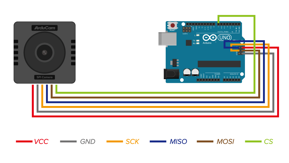
I returned to my quest of getting the Arducam Mega 3MP working anf have had no luck at all. I have created the following diagnosis program that might help someone else here:
My latest attempt was with an Arduino R4 WiFi and all I keep getting is connection failures and incorrect reads. I have tried various wiring changes and testing but still no luck at all.
I used the above wiring but to no avail. The code uses pin 10 for CS, which also doesn’t seem to work.
The result indicate it is detected by any reads and writes come back wrong. I have tried all sorts of timing changes to no avail. Thus, I’m going to shelve this for a while and move on with other things.
It really shouldn’t be this hard and I can only think that perhaps the camera has somehow been damaged in all my testing. Perhaps a new one and fresh start is in order?
The next controller I’m going to play with is the Arduino Uno R4 Wifi. I really like the ease and compatibility of the Arduinos I have used so far but the lack of WiFi I know will be a major limitation. So it make sense to explore a Wifi Uno.
One of the additional ‘nice’ features of the Arduino Uno R4 Wifi is that it has a LED matrix included on the board. Thus, the starting point is to try and get something to display on there.
First I tried displaying a simple emjoi. The code for this is here:
Now that I have my robot arm actually working, I can share the video of its operation above. It basically operates one servo at time to pick up and object and then place that object to the left. It will simply continue to do that over and over.
so it can run stand alone rather than plugged into a USB port to provide power, however it does work! Yippee!
I think this kit is a great starter option and I would have been much better off commencing my IoT journey here rather than going hard core with just a single processor. The way the kit takes your through individual components and concepts, all building to the final sun follower was fantastic. The instructions were easy to follow, provide great information making it super simple to move through all the steps.
This was my first time actually using an Arduino development board and I can now understand why it is such a popular option. There is no soldering, all you need to do is plug and play. The connections are colour coded and easy to access and understand. Reflecting on how easy this kit an dteh Arduino controller is make me regret going down the route I took and the extra hassle, such as soldering pins, to get my initial projects to even work. Geeze, I did it the hard way.
The challenge is that unless you know someone skilled in IoT you won’t know where to start. However, starting with something like this is really the way to go I would suggest. It allows to grasp the concepts and see results quickly which no only reinforces learning but makes things far less frustrating due to something like a bad soldering joint. I just wish someone had recommended I start with a project like this rather than they way I did.
I’m now a big fan of the Arduino development board and will be looking ot utilise it in a few upcoming projects I have in mind. I think the Arduino is also going to let me resurrect my stalled Arducam Mega camera project. However, if you are looking to get into IoT then look no further than the Keyestudio DIY Solar Tracking Kit I suggest.
During this process the LED on the add on board failed! Strange. I checked the port, the voltage and whole lot of other stuff, but as far as I can tell the LED itself failed! I therefore used the buzzer as substitute until I decided to ‘bodgy’ another LED I had laying around as a temporary substitute. Why? Well, this LED board is pretty handy for troubleshooting I’ve found.
The result is as shown above, both sound and light when the light sensor falls below a certain level.
I can’t find a replacement for the LED board on its own. Seems it only comes with full kits. I’ll need to look at buying a similar LED at some stage and maybe swapping the faulty on out on the board. It will be rather fiddly but worth the effort going forward I reckon.
Which I thought would be a good opportunity to jump back into things after all teh struggles I’ve had with the Arducam Mega 3MP. I need a few wins to lift my motivation, thus the purchase.
The brains of the kit is a Keyestudio KS0172:
The core processor of this board is ATMEGA328P-AU and ATMEGA16U2 is used as a UART-to-USB conversion chip.
It has 14 digital input/output pins (of which 6 can be used as PWM outputs), 6 analog inputs, a 16MHz crystal oscillator, a USB connection, a powerjack, 1 ICSP header, and a reset button. All you need to do is connect it to a computer via a USB cable and power it with an external power supply of DC 7-12V
Which seems much easier to interface.
Turns out this kit is actually a series of projects with the board, which is exactly what I wanted. Start simple and then extend.
First step was to get the board working with Platformio environment.
When I plugged the board into my PC it was automatically recognised as Arduino Uno as see above. Thus, when I set up Platformio I select Arduino Uno. This produced the following platformio.ini for me:
[env:uno] platform = atmelavr board = uno framework = arduino
I then wired up the LED board per the instructions in the manual like so: